
Self runner Generator
The described circuit utilizes a rotor equipped with a tiny magnet to create precise timing for generating high voltage spikes. The rotor's movement is essential for triggering a reed switch, which subsequently activates a relay. This relay is responsible for directing energy from a recovery coil to a primary battery while simultaneously isolating the rest of the circuit from the primary battery, ensuring that the system operates efficiently.
The recovery coil plays a critical role in this configuration. It is emphasized that the coil must possess a minimum resistance of 20 Ohms, with higher resistance being preferable. This characteristic is crucial because it directly affects the voltage generated across the recovery coil as the rotor's speed increases during startup. A voltmeter can be used to monitor this voltage, which is expected to rise as the rotor accelerates.
The generation of high voltage spikes, specifically reaching up to 2000V, is contingent upon the recovery coil producing a voltage of at least 30-35V. If the coil is unable to achieve this threshold, it is recommended to enhance the coil's design by adding additional turns of wire. This adjustment increases the coil's inductance and, consequently, its ability to generate higher voltages.
The arrangement of magnets in an NSNS configuration is critical for the timing of the relay activation. The positioning of the neo magnet is designed to trigger the relay at an optimal moment—specifically, just after the north pole of the first magnet has passed the primary power coil and immediately before the next north pole approaches. This precise timing is essential for maximizing the voltage spikes produced by the circuit, ensuring that the energy transfer is both efficient and effective.
Overall, the described circuit illustrates a method of harnessing mechanical energy through careful timing and configuration of components to achieve high voltage outputs, which can be utilized in various applications requiring such voltage levels.The timing must be exact to get those high voltage spikes. I used a tiny magnet on the rotor, that triggered a reedswitch allowing the relay to pulse the energy from the recovery coil to the primary battery. In the same time the rest of the circuit is disconnected form the primary battery. The recovery coil has to have at least 20Ohms resistance, the higher the better, because when the speed rises at startup, you can see on the meter, that the voltage across the recovery coil increases.
But the 2000V spikes start to appear only when about 30-35V are reached. So if your recovery coil can not generate at least 30 volts conventionally, it will be hard for you to get those high voltage spikes. If so, just add some more turns of wire on your coil. The magnets are in NSNS configuration. You must place the neo magnet so that it triggers the relay just after the N magnet has passed by the primary power coil and just before the next N magnet.
That way you will get the high voltage. 🔗 External reference
Related Circuits
This circuit is designed to demonstrate high-frequency high voltage, capable of producing voltages up to approximately 30 kV, depending on the transformer used. It is economical and straightforward to construct, primarily utilizing a standard TV flyback transformer. The circuit...
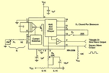
For measurement purposes in the electronics laboratory, signals of various frequencies and waveforms are frequently required. A standard function generator typically provides sine, triangular, and square wave outputs. The frequency must be adjustable and should encompass at least the...
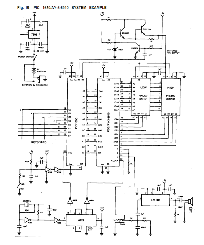
The AY-3-8910/8912 is a register oriented Programmable Sound Generator (PSG). Communication between the processor and the PSG is based on the concept of memory-mapped I/O. Control commands are issued to the PSG by writing to 16 memory-mapped registers. Each...

Six preset controls and seven selector switches enable a vast range of different sounds to be produced and altered at will. Such sounds as steam trains chuffing, helicopters flying, bird chirping, and machine guns firing are possible, as well...

This device was originally designed to test the Shutter Time Meter, which is specifically intended for analog SLR cameras. To accurately measure a camera's exposure time, it must first be checked with a well-defined signal. This circuit serves that...
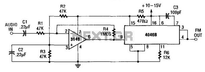
The internal zener diode on pin 15 of the 4046B provides a stable voltage to the 3140IC operational amplifier. This amplifier modulates the voltage-controlled oscillator (VCO) of the 4046B. The gain of the amplifier is approximately 20 (26 dB...