
Optical Pulse Generator
The circuit operates primarily on the principles of digital logic and timing. The 74HC4060 (IC1) functions as an oscillator, generating a stable clock signal based on the selected crystal frequency. This clock signal is critical for determining the timing of the output pulses. The dual decade counter (IC2) divides the frequency down to the desired pulse lengths, allowing for precise control over the output timing. The use of a Johnson counter (IC3) further refines the output, ensuring that the generated pulse is clean and free of glitches.
The design incorporates multiple jumpers for frequency selection, enabling versatility in testing different shutter speeds. The RC network used for pulse shaping and reset ensures that the system remains stable and responsive, preventing any unintended effects on the output pulse timing. The choice of LED and its characteristics are also critical, as they directly influence the performance of the circuit in practical applications. The circuit's low idle current consumption makes it suitable for battery-powered applications, while the brief increase in current during pulse generation indicates efficient operation without excessive power draw.
Overall, this circuit design exemplifies effective use of digital logic components to create a reliable and accurate pulse generator suitable for testing shutter time meters and potentially other applications requiring well-defined pulse signals.This little aid was originally designed to test the Shutter Time Meter. This meter was specifically designed for analogue` SLR cameras. In order to measure the exposure time of a camera accurately, it will first have to be checked with a well-defined signal first. This circuit was designed for that purpose. But the circuit can also be used if you need a well-defined pulse for some other purpose. The circuit is build around a trio of standard logic ICs. Firstly a 74HC4060 (IC1) is used to provide a quartz crystal accurate reference for the duration of the pulses. For the crystal frequency we choose the common 4. 096 MHz value. To test all the ranges of the shutter time meter, we choose three different pulse lengths in three different decades, namely: 1 / 2 / 4 / 10 / 20 / 40 / 100 / 200 / 400 ms.
With jumper J1 you select a frequency of 1000, 500 or 250 Hz (see table). The frequency is then passed on to J2 and the dual decade counter IC2 (a 4518). This does not need to be a fast HC-type, since the frequency is at most 1 kHz. With J2 the frequency can be reduced by 1, 10 or 100 times. This frequency is then applied to IC3 (a 5-stage Johnson-counter). This has been set up in such a way that in the end there appears only one single pulse at the output. The advantage of the Johnson-counter is that each output is free from glitches and has a duration that is exactly equal to the period of the clock input.
We choose Q2 as the output. Q4 is used to stop the counter. Q0 is only active if we push the reset-button S1. IC3 will then start to count. To ensure that the reset does not affect the duration of the pulse, a differentiating RC-network R4/C3 generates a short reset pulse. R3 ensures that C4 is discharged after releasing S1. Also, just to be sure, we don`t use the second counter output but use the third one instead. For the same reason, to stop the counter we use the fifth output. Especially with longer times you will notice that the pulse will arrive at the output a short time after pressing the switch.
R5 drives a current of nearly 20 mA through D1. D1 provides sufficient light for this application to trigger the receiver diode in the shutter time meter. An unusually fast type was selected for the LED, which, with a switching time of 40 ns, has practically no influence on the length of the pulse.
If you would like to use another LED then you will have to look closely at the switching time. This needs to be small compared to the duration of the pulse. If you want to use the circuit with a logic level output then you can just omit D1. If necessary, the pulse lengths can be changed be selecting another crystal frequency. The current consumption in the idle state is less than 2 mA. In our prototype, while the circuit is delivering a pulse, the current consumption increases briefly to about 18 mA. Do not forget the wire link under IC2 when assembling the circuit. 🔗 External reference
Related Circuits
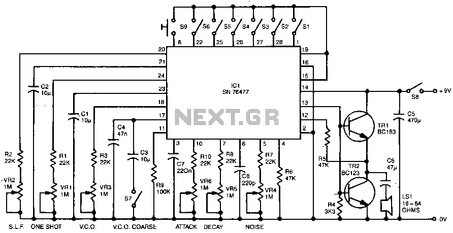
Six preset controls and seven selector switches enable a vast range of different sounds to be produced and altered at will. Such sounds as steam trains chuffing, helicopters flying, bird chirping, and machine guns firing are possible, as well...
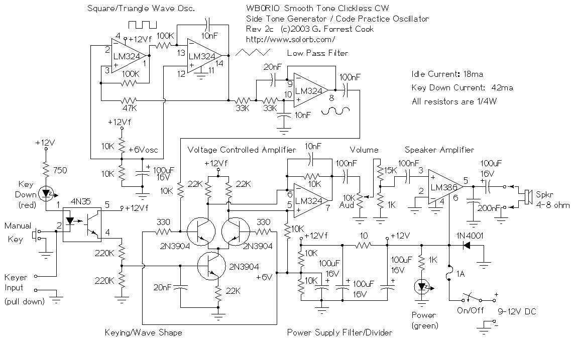
This circuit is about as good as it gets for generating morse code tones. It may be used as a code practice oscillator, a tone generator for a keyer, a sidetone oscillator for a CW transmitter or an audio...
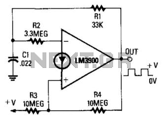
When the output is high, R3 and R4 are in parallel, and C1 charges through R1 until the current in R2 equals that at the non-inverting terminal. This action occurs when C1's voltage rises to 2/3 of the supply...
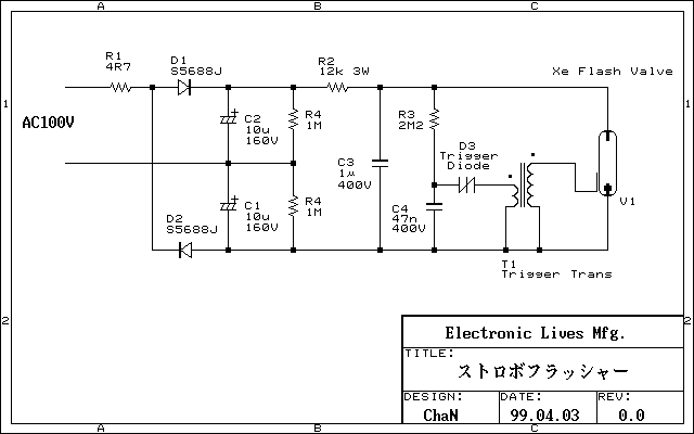
Flash lamp is made with experimental parts removed from a disposable camera flash circuit. Xenon try to use what I think is easily affordable experiment. AC100V to a voltage doubler rectifier, DC voltage of about 270V is derived. This...
This is a circuit for a Voltage-to-Pulse Duration Converter. The circuit is designed to convert voltage into pulse duration by integrating a timer IC and an operational amplifier (OP Amp). The Voltage-to-Pulse Duration Converter circuit utilizes a timer IC, typically...
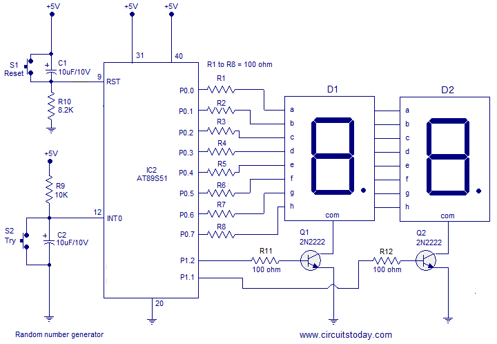
A simple random number generator utilizing the 8051 microcontroller. The AT89S51 is the controller employed in this setup. The circuit design for the random number generator based on the AT89S51 microcontroller involves several essential components and connections. The AT89S51 microcontroller,...
Warning: include(partials/cookie-banner.php): Failed to open stream: Permission denied in /var/www/html/nextgr/view-circuit.php on line 713
Warning: include(): Failed opening 'partials/cookie-banner.php' for inclusion (include_path='.:/usr/share/php') in /var/www/html/nextgr/view-circuit.php on line 713