
Sensitive Low-Current-Drain Motion Detector
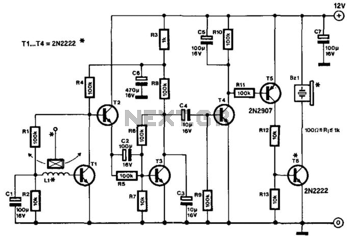
The first stage of the circuit employs a common emitter design with automatic regulation. The collector resistors and the resistors in the regulation bridge feature unusually high values. Feedback from the bridge ensures stable operation for transistor T1. An increase in collector voltage will be countered by an increase in base-emitter current, while a decrease in collector voltage will lead to a reduction in base-emitter current. As a result, the collector voltage stabilizes at a level corresponding to a base voltage of approximately 0.6 V. Capacitor C1 delays the immediate feedback effect when there are rapid changes in collector voltage. The minute voltage induced in the relay coil is significantly amplified by T1, as C1 prevents automatic regulation.
The output impedance of the first stage is very high, which is necessary for low power consumption. Following this stage with a low output impedance would negatively impact overall amplification. Consequently, T1 is followed by an emitter-follower configuration, T2, which facilitates the coupling between T1 and T3. Resistor R5 allows for a partial discharge of capacitor C2 when T2 is turned off due to a reduction in T1's output. Given the high value of this resistor, which is dictated by the low power consumption requirement, the circuit reaches maximum sensitivity approximately 10 seconds after the last movement detection, as this duration is required for capacitor C2 to stabilize its charge.
The actual detection is performed by T4, which activates when the voltage variations in the amplifier, transmitted through C4, reach 0.6 V. When T4 saturates, it triggers the immediate charging of capacitor C5. This capacitor partially discharges through resistors R10 and R11 to the base of T5 when T4 turns off. As C5 discharges, T5 becomes active, causing T6 to conduct, which in turn actuates a load, such as a buzzer, in T6's collector circuit. The sensitivity of the detector is heavily influenced by the distance between the magnet and the relay, as well as the length of the pendulum.
When powered by a battery, a potential issue arises due to the battery's high internal resistance. Consequently, the supply voltage may fluctuate by several tenths of a volt if a sudden, large current is drawn. If the buzzer stops after a detection, such fluctuations can retrigger the circuit, leading to undesired oscillations. To mitigate this problem, the amplifier stage's supply is decoupled using resistor R3 and capacitor C6.
This movement detector circuit exemplifies a well-designed system that balances sensitivity, stability, and power efficiency, making it suitable for various applications, including security and interactive gaming. This highly sensitive movement detector is designed from bipolar transistors and draws a curren t of only 0.3 mA during quiescent operation. It is intended primarily as a protection device, but it can also be used in certain games. The principle is simple: a magnet is suspended by a thin thread 20 to 30 mm long, and a few millimeters above the coil of a relay (whose contacts are not used). Even a minute movement of the protected object will disturb the magnet. The resulting changes in the magnetic field above the relay coil will induce a tiny varying voltage across the coil.
The first stage consists of a common emitter design with automatic regulation. The collector resistors and the resistors in the regulation bridge have unusually high values. Feedback from the bridge ensures stability of operation for Tl. Each increase in collector voltage will be opposed by an increase in base-emitter current. Conversely, each reduction in collector voltage will be opposed by a decrease in base-emitter current. Consequently, the collector voltage will stabilize at a value that corresponds to a base voltage of about 0.6 V.
Capacitor CI delays the immediate effect of the feedback when the collector voltage changes rapidly. The small varying voltage induced in the relay coil is magnified appreciably by Tl because CI prevents automatic regulation. The output impedance of the first stage is very high, which is, of course, the price to be paid for low consumption.
It would not make sense to follow this stage by one with a low output impedance, because this would adversely affect the overall amplification. Because of that, Tl is followed by an emitter-follower, T2, which provides the coupling between Tl and T3.
Resistor R5 allows a partial discharge of C2 if T2 is switched off by a reduction in the output of Tl. Because this resistor, as a result of the low-consump-tion requirement, has a high value, the circuit will attain its maximum sensitivity 10 seconds after the last movement detection.
This is the time that is required for the charge on capacitor C2 to stabilize. The detection proper is carried out by T4, which switches on when the voltage variations in the ampli- fier, passed on by C4, reach a level of 0.6 V. Saturating T4 leads to the instant charging of C5. This capacitor will discharge partly via RIO and Rll to the base of T5 when T4 switches off again. When C5 discharges, T5 is on, which will make T6 conduct. This in turn will actuate a load, for instance, a buzzer, in the collector circuit of T6. The sensitivity of the detector depends to a large extent on the distance between the magnet and relay and the length of the "pendulum." If the circuit is powered by a battery, there is a little problem: batteries have large internal resistances.
Thus, a supply voltage can vary by some tenths of a volt if a sudden, large current is drawn. If the buzzer has stopped after a detection, such a situation can retrigger the circuit and cause undesired oscillations. To prevent this happening, the supply of the amplifier stage is decoupled by R3 and C6. 🔗 External reference
Related Circuits
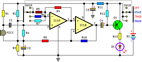
This circuit is designed to indicate, via a flashing LED, when room noise exceeds a predetermined threshold. The thresholds are set at three fixed levels: 50 dB, 70 dB, and 85 dB. Two operational amplifiers (op-amps) are utilized to...
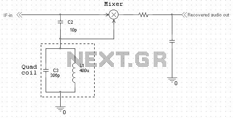
Quadrature FM detectors use a high-reactance capacitor (C2) to produce two signals with a 90 degree phase difference. The phase-shifted signal is then applied to an LC-tuned resonant at the carrier frequency (L1 and C3). Frequency changes will then...
A modification to David Knight's linear detector circuit was developed to create a high-fidelity AM receiver requiring an ultra-linear AM detector. The revised circuit eliminates the meter circuit and many bypass capacitors, resulting in a design with a finite...
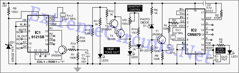
A DTMF-based infrared (IR) transmitter and receiver pair can be utilized to create a proximity detector. This circuit enables the detection of any object capable of reflecting the IR beam and moving in front of the IR LED and...
IC1 and IC2 form an inverting half-wave precision rectifier and peak detector circuit. Negative input signals that swing with peaks larger than the voltage on C1 cause this capacitor to charge to the new peak voltage. The capacitor retains...
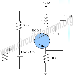
This project involves a simple metal detector circuit that is easy to construct using a single transistor and a few additional components. The circuit operates as a Colpitts oscillator, broadcasting on the AM band. To use it, place a...