
Hi-fi AM detector
The filter gets rid of the adjacent-channel carrier heterodyne whistle, which can be bad at night when the sky-wave comes in. It can be re-tuned for the European 9 kHz channel spacing as well. One reason for using Dave Knight`s method of linearizing the detector is that it fits well with a low voltage single supply.
As you can see I powered my 455 kHz. detector from 6 V and it has a buffered output. I discovered "Hi-Fi AM" quite by accident too. It can rival FM to some extent and some of the venues on AM here in Idaho are not available on FM. The input Z is high enough so that the detector circuit can drive directly into the notch filter with no additional buffering. Supply voltage for this circuit can vary between 5 V and 12 V with no ill effects. Voltage divider R5/R6 controls the circuit Q, R3 controls the center frequency but may interact with the Q (second order).
R5/R6 can be realized with a 1 k resistor in series with a 200 ohm trim pot. R3 can be realized with another 1 k resistor in series with a 200 ohm trim pot connected as a rheostat. This will allow trimming of the circuit to match the 18-20 dB notch and center frequency of 10 kHz. One of the problems with AM broadcast reception using a relatively wide IF bandwidth is that the stations transmit full carrier and the channel spacing is only 10 kHz (in America, 9 kHz in Europe).
Thus it is possible to receive a 10 kHz "whistle" when reception is good (such as at night). This high pitched noise is easy to hear for most people. The next channel is 20 kHz. away, which is out of typical adult hearing range, and the LPF in the detector attenuates it as well. Here is a good "whistle" filter for the MW band that doesn`t degrade the audio frequency response. Note that it is a bridged-T design and uses an op-amp. The filter is bootstrapped with feedback from the unity follower. It is possible that an emitter follower could be used as well for this, but the 383 k resistor requires a very high input impedance for the buffer amplifier.
The voltage divider formed by R5 and R6 will increase the Q as R5 is lowered and R6 is raised in value. Care must be used, however, as the notch depth is affected, and there is less notch depth as the Q increases.
The idea for the filter comes from National Semiconductor Linear Brief 5. This shows a full twin-T notch filter bootstrapped to improve the Q. I found that the same technique could be used to bootstrap a bridged T circuit. Here is a Hi-Fi AM superhet receiver using the linear detector discussed above. The whole thing fits on a small PC board pictured right. The linear detector is on the part of the PC board in the foreground, and the TO220 package to the left of it is an LM317 voltage regulator for the 6 V power rail. The front end circuit is shown below. It uses the NXP / Philips NE602 double-balanced mixer chip; or, as here, the SA612, which is a lower cost version.
C5 and C6 were NOT fitted in the final build. The NE602 / SA612 has diffe 🔗 External reference
Related Circuits
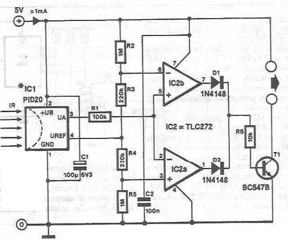
This infrared detector circuit is designed using the PID20 integrated circuit manufactured by Siemens, which converts thermal radiation into electrical impulses. It includes an operational amplifier and several electronic components. The output signal at pin 3 is compared with...
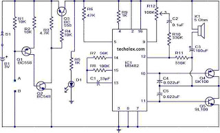
This is a simple alarm circuit that produces a musical tone when water or any conductive liquid comes into contact with the two sensor wires provided. The circuit utilizes four transistors and one melody generator IC (M3482). When water...
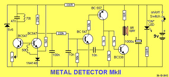
This project is an extension of Metal Detector MkI, demonstrating the detection of metal objects. It is the second in a series of circuits that allows significant experimentation, particularly for those with a Cathode Ray Oscilloscope (CRO) and various...
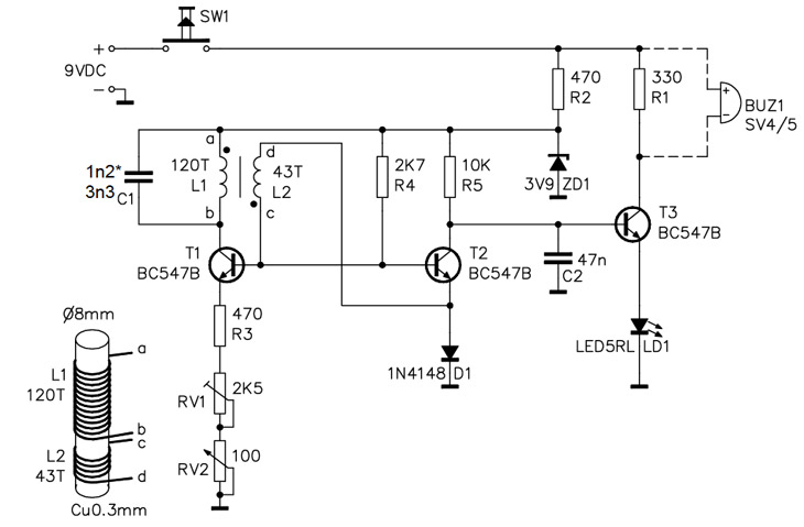
A simple home project can quickly become problematic if it encounters electric cables, gas, or water pipes, or the central heating system. Using a metal detector allows one to check for metal objects within walls, ceilings, or floors beforehand....
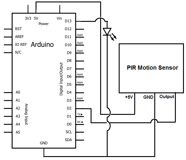
Once the motion sensor detects motion, the Arduino can be programmed to activate an LED, turn on a motor, sound a buzzer, etc. In this circuit, for simplicity, an LED will be turned on when the motion sensor detects...
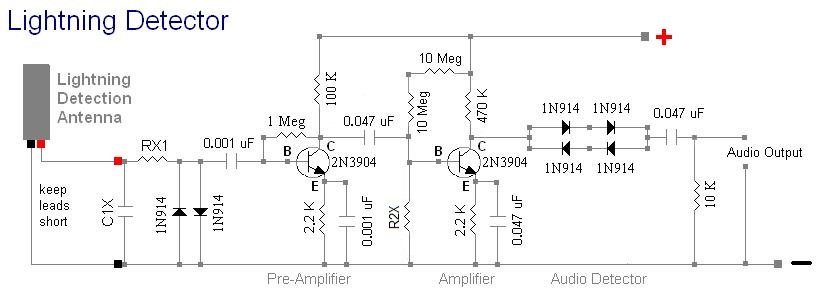
An audio amplifier connected to the output emits a loud click sound for each lightning strike detected. When severe storms approach, this receiver produces numerous clicks per minute. This is a direct detection amplified "crystal" radio receiver that does...