
Peak (Pulse) Voltmeter
 Voltmeter")
The Peak Voltmeter circuit is designed to accurately measure the peak voltage of fast pulse signals that would typically exceed the response time of standard voltmeters. The core functionality of this circuit is to stretch the duration of the pulse, allowing a slower voltmeter to register the peak value effectively.
The circuit typically consists of a diode, a capacitor, and a resistor. The diode is oriented to allow current flow only during the positive half-cycle of the pulse signal, effectively capturing the peak voltage. When the pulse arrives, the diode conducts, charging the capacitor to the peak voltage level. The resistor is used to discharge the capacitor slowly, providing a time constant that allows the voltmeter to display the peak value accurately.
In practical applications, the choice of the capacitor and resistor values is crucial. The time constant, determined by the product of the resistor (R) and capacitor (C) values (τ = R × C), must be sufficiently large to ensure that the capacitor retains the peak voltage long enough for the voltmeter to take a reading. This ensures that even if the input signal is a rapid series of pulses, the voltmeter can still provide an accurate peak measurement.
Additionally, the circuit may include an operational amplifier to buffer the voltage across the capacitor, improving the accuracy and stability of the measurement. The output can be connected to an analog or digital voltmeter, depending on the specific application requirements.
Overall, the Peak Voltmeter circuit is a vital tool in electronics, particularly in environments where quick voltage spikes are common, such as in power electronics, communication systems, and signal processing.This is a Peak Voltmeter circuit. This circuit can be viewed as a pulse stretcher, which catch fast pulse signal to be measured by a slow response voltmeter.. 🔗 External reference
Related Circuits

This design circuit is for converting voltage to frequency. Typically, frequency meters are used in speed sensors, tachometers, and for measuring recurring signals. The frequency to voltage converter (FVC) can transform voltage into either a digital or analog tachometer....
Below is a comparator circuit that can measure the voltage of a car battery in 1-volt steps. The voltage indication is achieved through a comparison mechanism. The described comparator circuit is designed to accurately measure and indicate the voltage level...
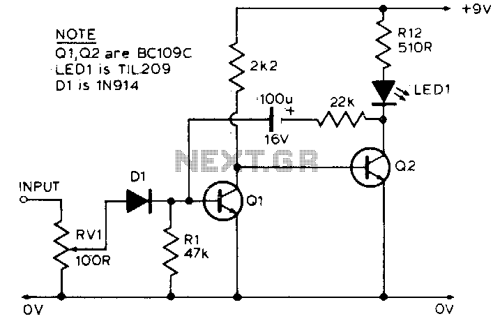
The LED is normally lit, but it will be briefly extinguished if the input exceeds a preset level (set by RV1). A possible application is to monitor the output voltage across a loudspeaker; the LED will flicker with large...
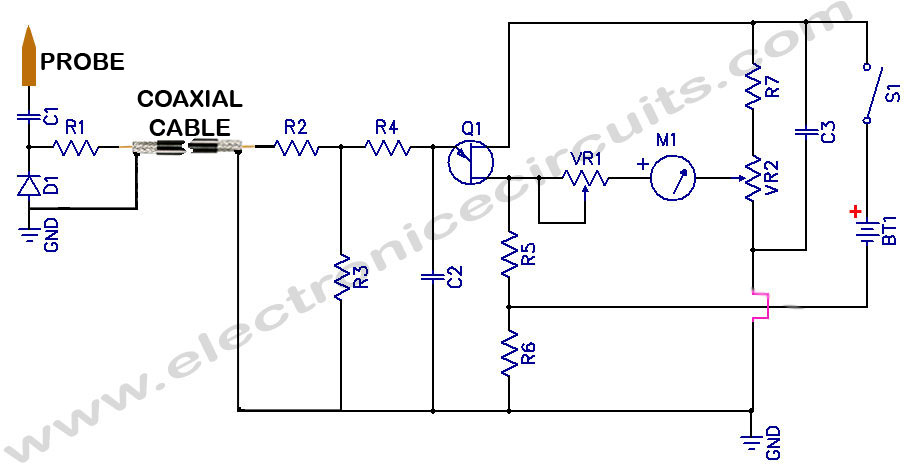
Sensitive RF Voltmeter Probe Circuit. This circuit measures RF voltages beyond 200 MHz and up to approximately 5V. The sensitive RF voltmeter probe circuit is designed to accurately measure radio frequency (RF) voltages in the range exceeding 200 MHz,...
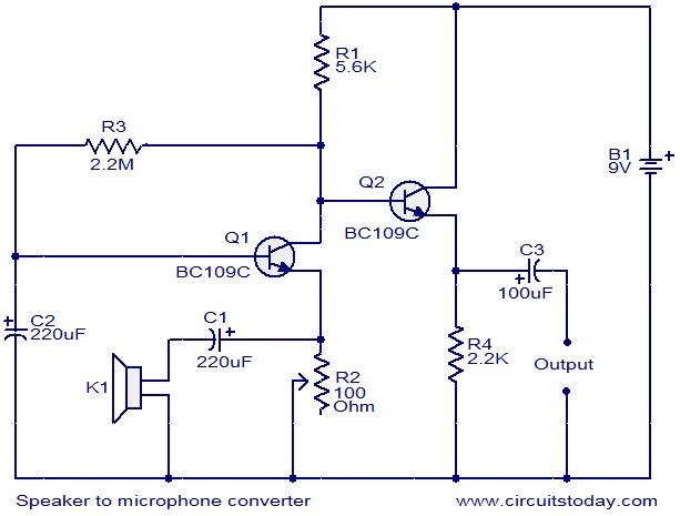
This circuit provides a straightforward method for converting a loudspeaker into a microphone. When sound waves impact the diaphragm of the speaker, fluctuations occur in the coil, generating a small induced voltage that is typically low in magnitude and...
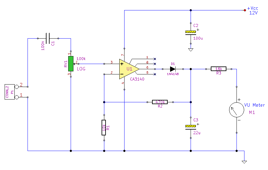
This simple circuit, designed with a minimal component count, indicates peak audio response on an analog meter, similar to a tape recorder's meter. It employs an operational amplifier configured as a non-inverting amplifier, with the addition of a diode...