
Light Sensitive Switch with LDR 2N2926
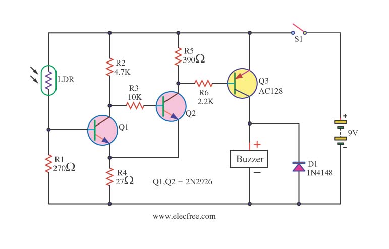
The described light-sensitive switch circuit is designed to detect ambient light levels and activate an output signal when the light intensity falls below a certain threshold. The core components of this circuit are the 2N2926 and AC128 transistors, which serve as the primary switching elements.
The operation of the circuit begins with a light-dependent resistor (LDR) that senses the light level. The LDR is connected in a voltage divider configuration with a fixed resistor. As the ambient light decreases, the resistance of the LDR increases, causing the voltage at the junction of the LDR and the resistor to rise. This voltage is fed into the base of the 2N2926 transistor.
The 2N2926 is configured as a switch. When the voltage at its base exceeds a certain threshold, the transistor turns on, allowing current to flow from the collector to the emitter. This current can be used to activate an alarm or indicator light, signaling that it is dark. The AC128 transistor may be used in conjunction with the 2N2926, possibly in a Darlington pair configuration, to amplify the current and improve the sensitivity of the circuit.
Additional components may include capacitors for noise filtering and diodes for protecting against reverse polarity. The circuit can be powered by a standard DC power supply, with appropriate voltage and current ratings to ensure reliable operation of the transistors.
This circuit can be applied in various applications, such as outdoor lighting systems, security alarms, or automatic night lights, providing a simple yet effective solution for light detection and response.This be circuit warn when be become dark, or Light sensitive switch. By use electronics part the base is important , be the transistor 2N2926 and AC128. For. 🔗 External reference
Related Circuits

An efficient automatic solar garden lights circuit with minimal components. The advantage is that it operates entirely autonomously, with the solar panel functioning as a light detector. It switches the lamp off at dawn, charges the battery during the...
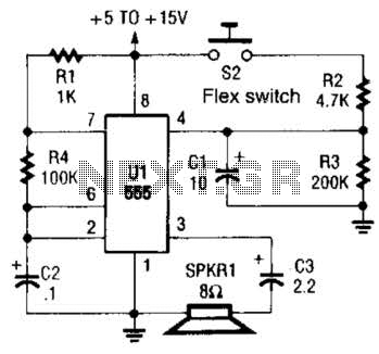
This is a cross-sectional diagram of a flex switch. They can be used as pushbuttons or even position sensors. This schematic diagram shows an oscillator, which is used as an alarm sounder, triggered by a flex switch. The flex switch...
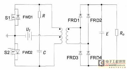
With the increase in the variety of modern electrical equipment for vehicles and the rise in power levels, there is a growing demand for different types of power supplies, including AC and DC sources. The power system needs to...
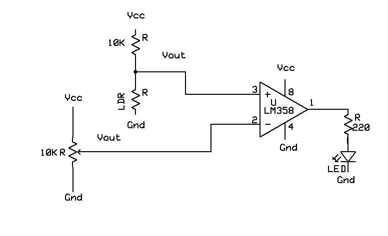
A light-based sensor utilizing an LDR (Light Dependent Resistor) and an operational amplifier (Op Amp). This circuit can be employed for applications such as line followers. The operation of the Op Amp is foundational to this design. It features...
The electronic switch consists of the CK-4 type magnetic control switch and the components VT1, R1, and R2. When the bathroom door is closed, the permanent magnet ZT and the reed switch GA come into proximity, which separates the...

This is a simple update to Mr. Hareendran's PIR Sensor Security Light circuit. It has a shortcoming that limits the relay voltage to approximately 3.3V. While this may function with some 5V relays, it will not function with all. The...