
Sensor-Activated Relay Pulser Circuit

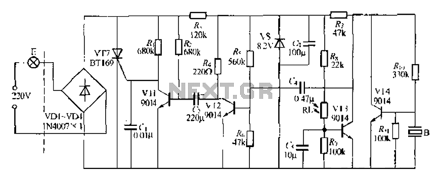
The circuit utilizes a low-frequency NE555 timer configured in astable mode to generate a square wave output that drives LAMP II. The sensor's operation is critical, as it determines the conditions under which the NE555 timer activates. The choice of RA or RB as the sensing element allows for flexibility; either can be a thermistor for temperature sensitivity or a photoresistor for light sensitivity.
In this configuration, RA and RB should not exceed 100 kΩ to ensure proper functioning of the oscillator. The values of these resistors will influence the timing characteristics of the NE555, specifically the frequency and duty cycle of the output signal. The pulse width and frequency can be adjusted by varying the resistance values and the capacitance connected to the timing pins of the NE555.
When the sensor detects a decrease in resistance (for instance, a rise in temperature) at RB or an increase in resistance at RA (like a decrease in ambient light), the NE555 timer is triggered to output a pulse. This output pulse activates Q1, allowing current to flow through LAMP II, thereby illuminating it. The design can be further refined by incorporating additional components such as diodes for flyback protection, capacitors for noise filtering, and potentiometers for fine-tuning the sensitivity of the sensor.
Overall, this circuit provides a simple yet effective means of controlling a lamp based on environmental changes, showcasing the versatility of the NE555 timer in various applications. A sensor turns on Ql to activate the low-frequency 555 oscillator, which pulses LAMP II. Sensor may be sensitive to changes in light or temperature. Either RA or RB can be sensors, as desired. A decrease in RB or an increase in RA will cause the NE555 to flash M. fl and RB should be 100 kohm max. 🔗 External reference
Related Circuits

Robot eyes circuit of Service. A simple circuit to simulate a man appointed to it. It consists of a dual-lamp working in an unsteady manner. Circuit diagram. The robot eyes circuit is designed to create a visual effect that simulates...

A Siemens SLB0586A IC enables the creation of a straightforward touch-controlled dimmer circuit. This circuit regulates a triac AC switch, allowing control of loads ranging from 10 to 400 W. The Siemens SLB0586A integrated circuit is designed to facilitate the...

Four application examples are presented in the figure, focusing on a three-phase brushless DC motor used in Winchester disk drives with an operating speed of 3600 RPM. Although the original design specifies an operating speed of 3600 RPM, alternative...

The circuit described is straightforward yet efficient in its operation. The transistor Tr1 is utilized in a grounded base mode, with an input directed to its emitter to facilitate a low impedance input. The circuit is designed to operate effectively...
A modified piezoelectric ceramic acoustic-electric transducer is utilized to create a sound and light control system for a stairway walkway with a delay lighting switch. The circuit structure is relatively simple, consisting of diodes VD1 to VD4 and a...
The circuit consists of two synchronized multivibrators formed by a pair of 555 timer circuits. It is capable of generating two synchronized pulse signals, with the spacing and frequency adjustable by modifying the time constant. The circuit offers flexibility...