
Sensor

The design of the line follower robot circuit involves several key components that work together to facilitate efficient line tracking. The sensors, positioned strategically on the robot, detect the contrast between the line and the background. The output from these sensors is fed into the operational amplifier, which functions as a comparator to convert the analog signals into digital signals suitable for processing by the microcontroller. This step is crucial, as microcontrollers typically require inputs to be within specific voltage ranges to interpret them correctly.
The choice of the LM324 operational amplifier is beneficial due to its four-channel configuration, allowing multiple sensors to be connected without the need for additional components, thus reducing complexity and potential points of failure. The sensitivity adjustment via R9 is particularly important, as it allows for fine-tuning of the sensor's responsiveness to varying light conditions, which can significantly affect the robot's performance.
In addition to the basic sensor configuration, integrating a camera can further enhance the robot's tracking capabilities, providing a higher-resolution view of the line and enabling more precise navigation. This advanced setup may involve additional processing power and software algorithms to interpret the camera data effectively.
Overall, the line follower robot circuit is a sophisticated integration of hardware and software, where each component plays a vital role in achieving accurate and reliable line tracking. The careful selection of sensors, operational amplifiers, and microcontrollers ensures that the robot can navigate complex paths with agility and precision.The article "Creating a Line Follower Robot with AVR [Censorship]" is a continuation of Line Follower Robot article with a new AVR ATMega8535 samapai phase Line Follower Robot block diagram. In the article "Creating a Line Follower Robot with AVR Part 1 [Sensor]" This is a review of the sensor used on Line Follower Robot, and the components used.
Sensors, can be analogous to the `eye` of a robot that serves to `read` the black line of the track robot or vice versa. So that the robot is able to know when he will turn right, when he turned left and when he stopped. Sensors used are usually photo reflector, LDR (Light Dependent Resistor), Photo Diodes and Photo Transistor - mounted on the front two or more below the line follower robot.
There also are using the camera as a sensor (or image sensor) to a higher-resolution readout line, making more accurate robot motion. The working principle of the sensor is simple, when the transmitter (infrared) emitting light onto a white field, the light will be reflected back to the receiver by the white areas and vice versa.
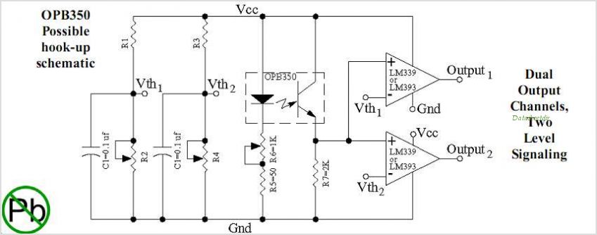
This gives the change in the voltage level at the receiver output, but it usually changes the voltage can not be accepted as a TTL logic level. To be able to read by the microcontroller, the sensor voltage should be adjusted to TTL voltage level that is 0-1 volts for logic 0 and 3-5 volts for logic 1.
This can be done by installing the operational amplifier is used as a comparator as shown in the picture above. Op Amp is used as a comparator LM324 IC, because IC is able to work at VCC 5 volt range and there are 4 in 1 Op Amp IC corresponding to the number of sensors are used.
The sensitivity of this sensor can be set through R9 which controls the comparator reference point. Line follower robot sensors can be made with a combination between LED and photo diode. Line follower robot sensor configuration is good to be able to read the track with a hard and fast. To make the robot sensor is firm and fast can not merely rely on the ability of photo diodes and LED configurations only. As an alternative to maximize the performance of line follower robot sensors can be added to the voltage comparator with Op-Amp.
sensor circuit line follower robot equipped with a voltage comparator that is ready to be connected to a microcontroller or PIC can use the following series of robot sensor. 🔗 External reference
Related Circuits
The PCD3360 is a CMOS integrated circuit designed to replace the electro-mechanical bell in telephone sets. It meets most postal requirements, featuring selectable output tone sequences and input ringer frequencies. The circuit provides output signals suitable for driving a...
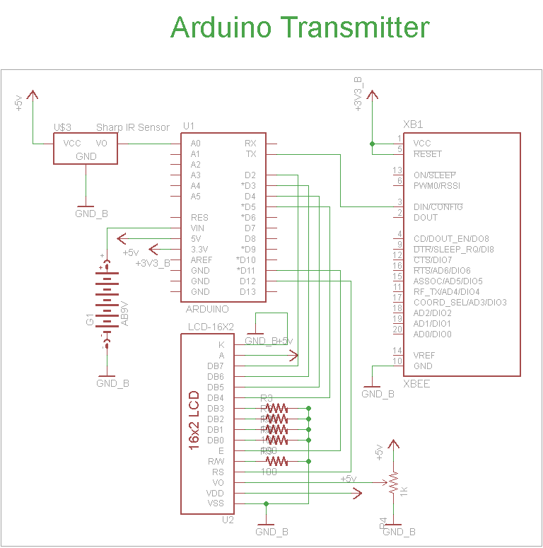
The schematic for the transmitter in this project consists of four main components: the Arduino UNO, the Sharp IR distance sensor, the XBee wireless modules, and a 16x2 LCD. The connections between these components are illustrated in the schematic....
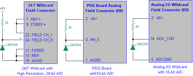
Interfacing the LM335A temperature sensor with A/D converters involves measuring temperature using the LM35 and LM335A sensors alongside the 9S12 HCS12 microcontroller. This process includes analyzing both calibrated and uncalibrated temperature errors of integrated circuit temperature sensors. The LM335A is...
This two-part article explains the utilization of a simple voltage divider circuit incorporating a thermistor to obtain high-accuracy temperature readings across a wide range of measurements. The first part focuses on the circuit design and explores various methods for...
The following circuit illustrates a LEGO Light Sensor Circuit Diagram. This circuit is based on the LM358 integrated circuit, which features a dual operational amplifier and high-speed capabilities. The LEGO Light Sensor Circuit utilizes the LM358, a versatile dual op-amp...
This design circuit is for a mass air flow (MAF) sensor. The MAF sensor converts the volume of air entering the engine into a voltage signal. The main components of the MAF sensor include a thermistor, a platinum hot...