
LEGO Light SensorCircuit With LM358 IC
The LEGO Light Sensor Circuit utilizes the LM358, a versatile dual op-amp IC, to create a light detection system suitable for various applications, particularly in robotic and automation projects using LEGO components. The circuit typically includes a light-dependent resistor (LDR) that changes its resistance based on the intensity of ambient light. This change in resistance is fed into one of the op-amps in the LM358, which is configured as a voltage comparator.
In this configuration, the LDR is connected to a voltage divider circuit, allowing it to produce a varying output voltage that corresponds to the light level. The second op-amp can be used to amplify the signal from the LDR or to provide additional processing, such as filtering or further comparison against a reference voltage. The output of the first op-amp can be connected to an LED or another actuator, enabling the circuit to respond to changes in light conditions.
This circuit can be employed in various applications, including automatic lighting systems, light-following robots, or as part of a larger LEGO robotics project. The simplicity of the LM358 allows for easy integration and modification, making it a popular choice for hobbyists and educators looking to explore the principles of electronics and sensor applications.The following circuit shows about LEGO Light Sensor Circuit Diagram. This circuit based on the LM358IC. Features: dual opamp,high speed double .. 🔗 External reference
Related Circuits
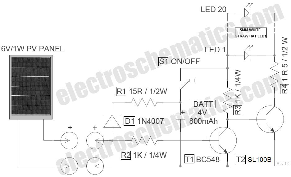
The circuit for the LED solar lantern lights is designed using a 6V/1W solar panel (photovoltaic panel) and a 4V/800mAh lead-acid battery. The schematic for the LED solar lantern circuit incorporates a solar panel that converts sunlight into electrical energy....

The hardware within this circuit involves a Picaxe 18M2 integrated circuit, which serves as the programmable microcontroller in the design and can be programmed using a PC. The Picaxe 18M2 microcontroller is a versatile device that is well-suited for a...
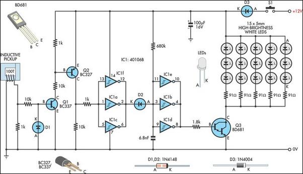
A timing strobe can be constructed using high-brightness LEDs and a few common components. Ignition pulses from the number one cylinder high-tension lead are used to trigger the circuit via a homemade inductive pickup. Transistors Q1 and Q2 buffer...
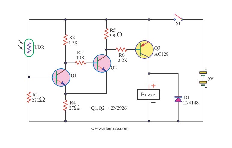
This circuit activates a warning when it becomes dark, functioning as a light-sensitive switch. The essential electronic components include the 2N2926 and AC128 transistors. The described light-sensitive switch circuit is designed to detect ambient light levels and activate an output...
Efficient automatic solar garden lights circuit with minimal components. The advantage is that it operates completely automatically, with the solar panel serving as a light detector. The efficient automatic solar garden lights circuit is designed to provide illumination using renewable...
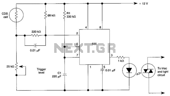
This circuit can control the on/off cycle of a light using a CDS photocell and turn it off after a preset period. The light can only be activated when the CDS cell is in darkness, and it remains on...
Warning: include(partials/cookie-banner.php): Failed to open stream: Permission denied in /var/www/html/nextgr/view-circuit.php on line 713
Warning: include(): Failed opening 'partials/cookie-banner.php' for inclusion (include_path='.:/usr/share/php') in /var/www/html/nextgr/view-circuit.php on line 713