
AVC Automatic Volume Control Circuit
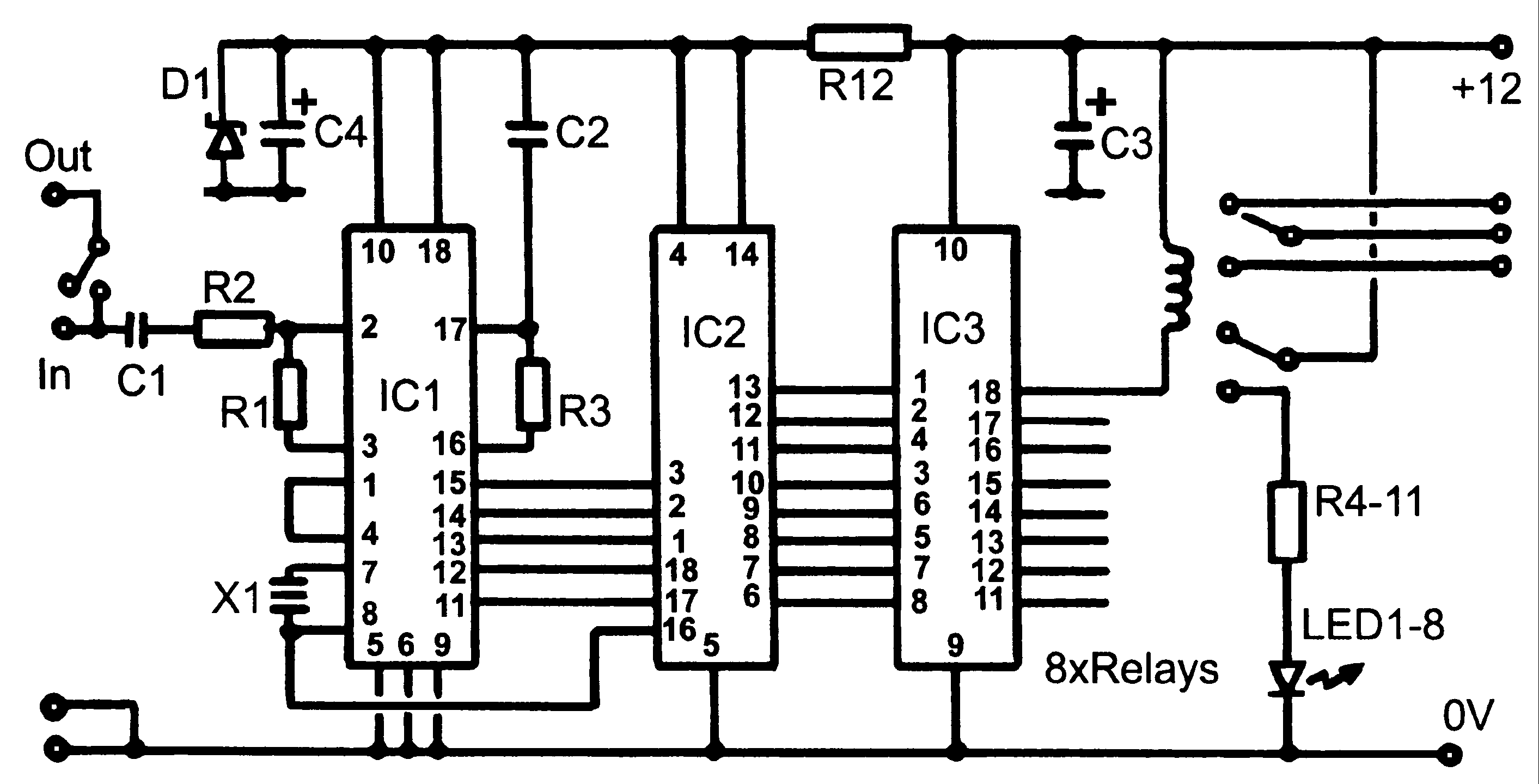
The Automatic Volume Control (AVC) circuit is designed to manage audio levels dynamically, ensuring a stable output that enhances the listening experience. The circuit operates by monitoring the audio signal and adjusting the gain as necessary to maintain a predetermined output level, in this case, around 4 volts peak to peak.
The AVC circuit typically consists of several key components, including operational amplifiers, resistors, capacitors, and diodes. The operational amplifiers serve as the main processing units, amplifying the audio signal while also providing feedback for automatic adjustment. The resistors and capacitors are used to set the time constants of the circuit, determining how quickly the AVC responds to changes in the input signal.
In operation, the circuit first detects the incoming audio signal's amplitude. If the amplitude exceeds a certain threshold, the AVC reduces the gain to prevent distortion and maintain a consistent output level. Conversely, if the signal amplitude is lower than the threshold, the circuit increases the gain to ensure that the output remains at the desired level.
The design of the AVC circuit can vary depending on the specific application and requirements. For instance, in a high-fidelity audio system, additional filtering may be incorporated to minimize noise and improve sound quality. In contrast, a simpler design may suffice for basic applications where audio quality is less critical.
Overall, the AVC circuit plays a crucial role in audio systems by providing automatic volume adjustment, enhancing user experience, and protecting against sudden volume spikes that could damage speakers or impair sound quality.AVC - The featured circuit controls a volume line automatically. It delivers an output voltage of approximately 4 volts peak to peak. This voltage remains.. 🔗 External reference
Related Circuits
Control monitoring equipment at a TV repeater site is designed to accept commands sent as DTMF tones over the repeater's audio channel. It is capable of switching either AV signals or power supply feeds with currents up to 1...
Some simple 555 and flip-flop circuits are being developed to add electronic lighting effects to modernize games. Various circuits are being collected for different game aspects, such as idle states, flipper shots, flower openings, winning shots, etc. A collection...
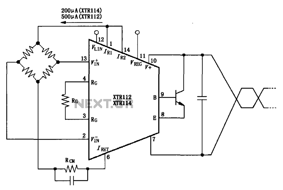
The two current sources within the chip (1 foot and 14 feet out) provide excitation. The output of each current source is 0.2 mA (XTR114) or 0.5 A (XTR112). The common mode input voltage is adjustable, ranging from 1.25...
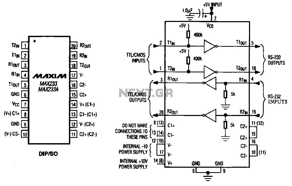
The MAX233 / 233A is a multi-channel data interface circuit featuring dual output and dual input driver circuits. It is designed for small digital products and multimedia equipment to facilitate data transmission. The MAX233 / 233A integrates multiple functions to...
The automatic sprinkler controller circuit consists of a power supply circuit and a humidity measurement and control circuit, as illustrated in the accompanying figure. The power supply circuit includes a power transformer (T), rectifier diodes (VD1 to VD4), filter...
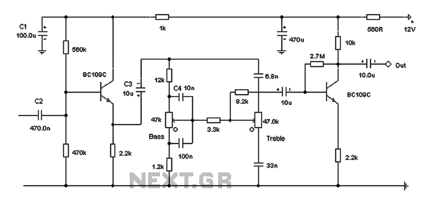
Based on the classic Baxendall tone control circuit, this design offers a maximum cut and boost of approximately 10 dB at 10 kHz and 50 Hz. Since the controls are passive, the final transistor provides a slight boost. The...
Warning: include(partials/cookie-banner.php): Failed to open stream: Permission denied in /var/www/html/nextgr/view-circuit.php on line 713
Warning: include(): Failed opening 'partials/cookie-banner.php' for inclusion (include_path='.:/usr/share/php') in /var/www/html/nextgr/view-circuit.php on line 713