
sepic converters solve automotive power
The Single-Ended Primary Inductance Converter (SEPIC) is a type of DC-DC converter that enables efficient voltage conversion while maintaining electrical isolation. It is particularly advantageous in automotive applications where the input voltage can vary significantly due to changes in battery state-of-charge or load conditions. The SEPIC topology utilizes two inductors, a switching element (typically a MOSFET), a diode, and a capacitor to regulate the output voltage.
In a SEPIC converter, the input voltage is applied to the primary inductor, and when the switch is closed, energy is stored in this inductor. The duty cycle of the switching operation determines the amount of energy transferred to the output. When the switch opens, the stored energy in the inductor is released through the diode, charging the output capacitor and supplying power to the load.
One of the key advantages of the SEPIC topology is its ability to step up or step down the input voltage, making it versatile for a range of applications. The output voltage can be controlled by varying the duty cycle, which can be adjusted to maintain a constant output despite fluctuations in the input voltage. This is particularly useful in automotive systems where the input voltage from the battery may vary widely.
Additionally, SEPIC converters exhibit lower output ripple compared to other topologies, such as buck or boost converters, due to the continuous conduction mode operation. This characteristic is crucial in automotive applications where stable voltage levels are required for sensitive electronic components.
Furthermore, the design of the SEPIC converter can be optimized for efficiency by selecting appropriate component values, such as the inductance, capacitance, and switching frequency. Careful consideration of these parameters can lead to reduced losses and improved thermal performance, enhancing the reliability of the converter in automotive environments.
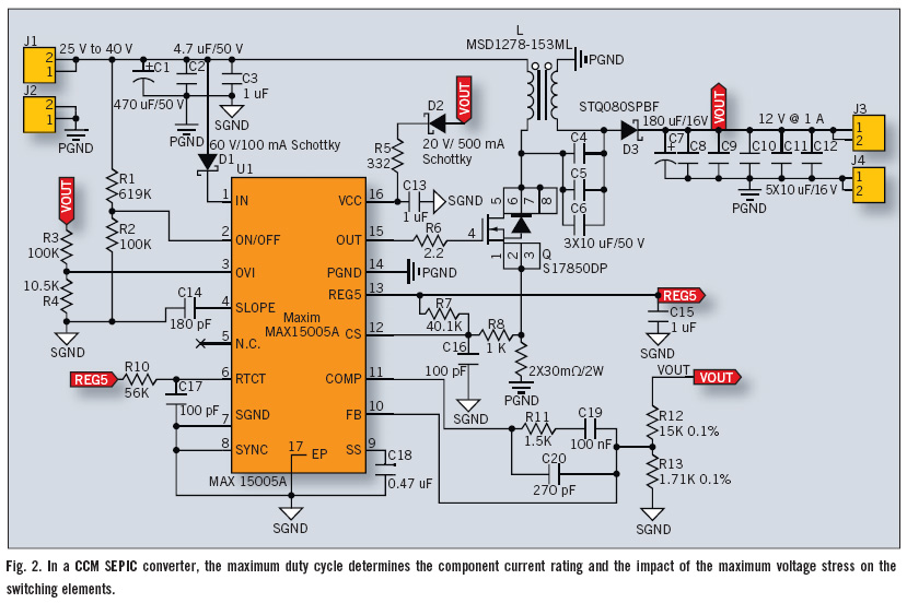
In summary, the SEPIC topology is a robust solution for automotive power systems, providing flexibility in output voltage regulation and efficient energy conversion, making it a preferred choice for modern automotive electrical architectures.Single-ended primary inductance converter (SEPIC) topology is a good choice for automotive power systems that require an output voltage between the low and high values of the input voltage. SEPIC topology fits this application because its duty ratio can be varied around 50% to provide an output voltage that is either below or above the input voltage.
Additionally, compared to flyback converters, SEPIC.. 🔗 External reference
Related Circuits
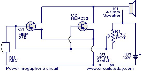
Any power transistor can be used in this megaphone, which is suitable for boats, playing fields, and similar applications. The transistors Q1 and Q2 are of the HEP-230 type, which are readily available in the market. These transistors are...

The circuit is designed to regulate a dual power supply that provides +12V and -12V from the AC mains. Such a power supply is an essential tool for an electronic hobbyist's workbench. The schematic of the circuit includes components...
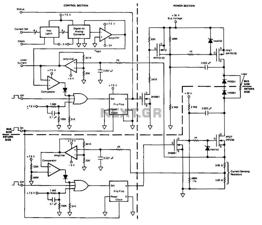
This circuit facilitates on/off switching, soft starting, current monitoring, current tripping, and overcurrent protection for a 30 Vdc power supply, accommodating normal load currents of up to 2 A. The switch is activated by an "on" command pulse and...
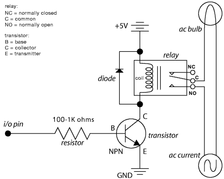
A circuit that allows a microcontroller to toggle a GPIO pin for shutting down the entire system, including the microcontroller itself. The system is normally powered down. When a momentary button is pressed by the user, power is restored....
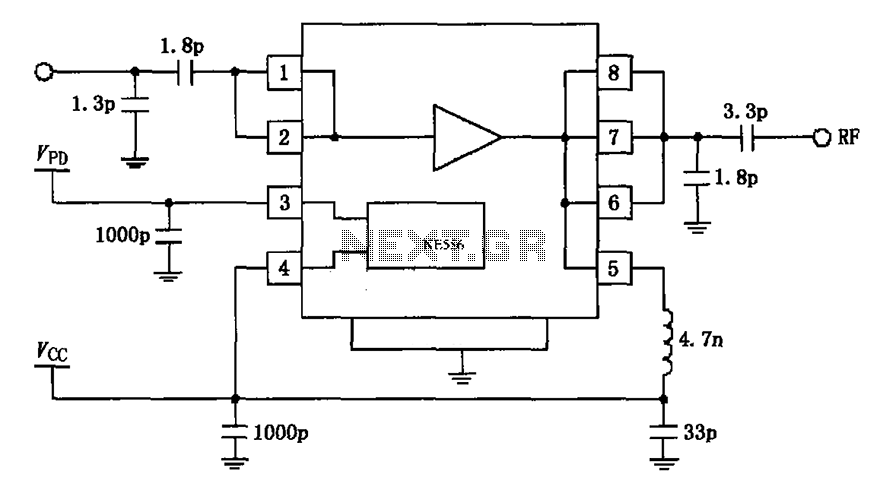
The circuit depicted in the figure is based on the RF2126, a 2450 MHz end-stage linear power amplifier. The radio frequency (RF) signal enters through input pin 1 and is subsequently amplified by the amplifier stages (pins 5, 6,...

The following circuit is a power amplifier circuit for an FM transmitter with an output power of 30 watts. The power amplifier circuit utilizes a power transistor of type 2SC1946A. The FM transmitter operates with a 13.8-volt DC power...
Warning: include(partials/cookie-banner.php): Failed to open stream: Permission denied in /var/www/html/nextgr/view-circuit.php on line 713
Warning: include(): Failed opening 'partials/cookie-banner.php' for inclusion (include_path='.:/usr/share/php') in /var/www/html/nextgr/view-circuit.php on line 713