
Sequence timer diagram composed by NE555
The NE555 timer is a versatile device commonly used for timing applications. In this particular configuration, it operates in a monostable mode, meaning it produces a single output pulse in response to a trigger signal. The relays K1, K2, and K3 serve as switches that can control larger loads, activating or deactivating external devices based on the timer's output.
The resistors RP1, RP2, and RP3, along with the capacitor C1, determine the timing interval of the circuit. The time period during which the output remains high can be calculated using the formula T = 1.1 * R * C, where T is the time in seconds, R is the resistance in ohms, and C is the capacitance in farads. By varying the values of RP1, RP2, and RP3, the user can customize the timing intervals to suit specific application requirements.
The connection of pins 2 and 6 ensures that the timer is retriggered as long as the voltage at pin 2 remains below 1/3 of the supply voltage. When the capacitor C1 charges, it eventually reaches a threshold voltage, causing the output at pin 3 to go high. The processed waveform output is essential for generating a clean trigger pulse, which is necessary for the reliable operation of the NE555 timer.
Overall, this circuit is suitable for applications such as timed control of motors, lights, or other devices requiring precise timing sequences. The simplicity of the NE555 timer, combined with the relay outputs, makes it an effective solution for various automation tasks.This is the sequence timer diagram composed by NE555. The timer can set time any time when the power is connected, break and control the external system to work. In the circuit, K1-K3 are relays used to control the corresponding system to work, adjust the resistance of the RP1-RP3, which can change the break time of the relay.
The pin 2 and 6 of NE555(1) connected together, when the power is connected, if the NE555(1) works, C1 charges instantaneously and the charging current flows through pin 2 to C1. At the same time, a waveform output from the pin 3 of NE555(1) forms a trigger pulse after color processed by the G1, which is added to the pin 2 of NE555(1) and make it work.
🔗 External reference
Related Circuits
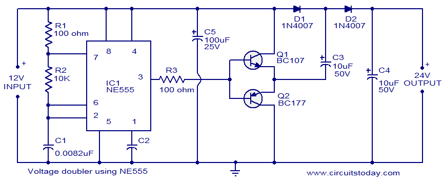
This circuit demonstrates a voltage doubler utilizing the NE555 timer. It is a straightforward project. The NE555 integrated circuit is configured as an astable multivibrator. The NE555 timer is a versatile component commonly used in various electronic applications, including timing,...
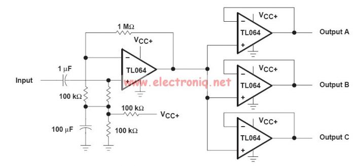
This audio distribution electronic project circuit diagram is designed using the TL064 or TL06 operational amplifiers and some other common electronic parts. The audio distribution circuit utilizes TL064 or TL06 operational amplifiers, which are quad op-amps known for their low...
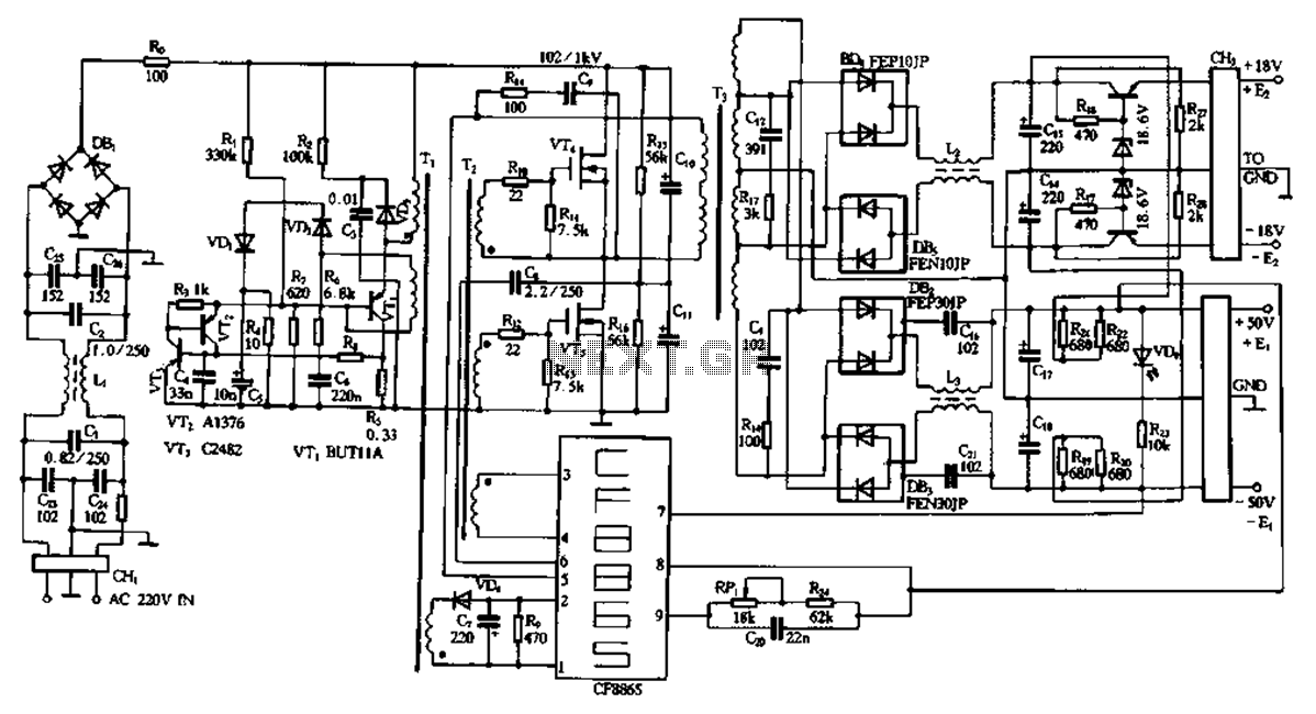
This document describes a specific module utilizing the CF8865 switching power supply circuit, which employs the integrated control module CF8865. In the figure, transistors VT4 and VTs are controlled by the excitation transformer Tz. The output is processed through...
This project is classified as intermediate to advanced, and it is not recommended for beginners in synthesizers or electronics. The circuit and some explanations are provided, assuming prior experience in project building, troubleshooting, and electronics. Ownership of electronic equipment...
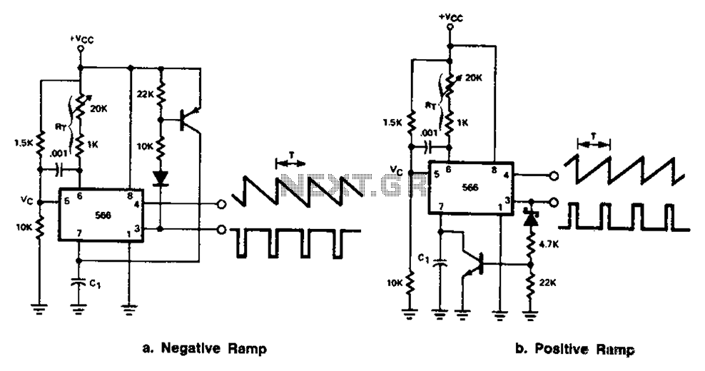
The 566 can be connected to either a positive or negative ramp generator. For a positive ramp generator, an external transistor is driven by the output pin 3. At the end of charging, C1 discharges quickly, allowing for immediate...
The two circuits below illustrate using the 555 timer to close a relay for a predetermined amount of time by pressing a momentary N/O push button. The circuit on the left can be used for long time periods where...