
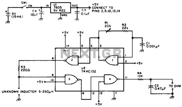
Sequential timing control circuit diagram

The timing control circuit operates as a sequential logic system designed to manage the operation of two switches in a predetermined timed sequence. This circuit typically employs flip-flops or counters to generate the necessary timing intervals, allowing for precise control over the activation and deactivation of the switches. The adjustable timing feature is often realized through the use of variable resistors or capacitors, enabling users to set the desired time delay according to specific application needs.
In scenarios where mechanical control is required for reciprocating motion, the circuit can be configured to alternate the state of the switches, thereby controlling the direction of a motor. This functionality is particularly useful in applications such as automated machinery, where forward and reverse motion is needed for tasks such as material handling or assembly processes.
The circuit design may include additional components such as diodes for protection against back EMF generated by the motor, as well as transistors or relays to handle the current required to drive the motor. The integration of these components ensures reliable operation while safeguarding the circuit from potential damage due to inductive loads.
Overall, this timing control circuit provides a versatile solution for applications requiring timed control of mechanical systems, facilitating both forward and reverse motor operation in a controlled manner. As shown in the timing control circuit is a sequential circuit, the circuit can be carried out sequentially timed control of the two switches, control time can be adjusted from a few seconds to several tens fair share; if mechanical control for reciprocating movement of positive and negative, can be It causes the motor to run forward and reverse timing requirements.
Related Circuits
The adjustable voltage monitor can be used to check whether the voltage in a circuit remains within a given range. If the DC voltage is less than the voltage at pin 5 of U1-B, then LED1 will light. If...
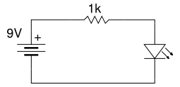
Beginner's Tutorial 1: Building a Circuit on Breadboard - how to build a simple and easy circuit on a breadboard for beginners in electronics. Learn to use an LED and a resistor. This tutorial serves as an introductory guide for...
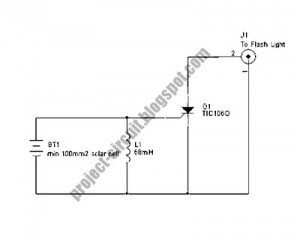
The following circuit illustrates a Slave Flash Light Control Circuit Diagram. Features include a 68mH inductor that provides an automatic trigger for the secondary flash light. The Slave Flash Light Control Circuit is designed to manage the operation of a...
This project utilizes a microcontroller that is programmed with software available on the Gernsback BBS at 516-293-2283 as part of RUNABOUT.ZIP. The robot can be operated using a universal remote control. The project involves the integration of a microcontroller, which...
It is easy to miss the sound of a doorbell while watching TV. This circuit addresses the issue by providing a visual indication, such as a lamp or an LED. Connecting a lamp directly in parallel with the doorbell...
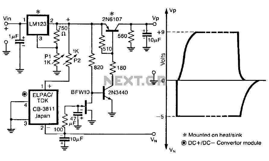
The control circuit is designed to operate by doubling a positive supply, which activates the first door when powered on and deactivates when the first drain is engaged, as illustrated in the accompanying figure. This circuit incorporates the LM123,...