
Serial communication between AVR-006 & computer
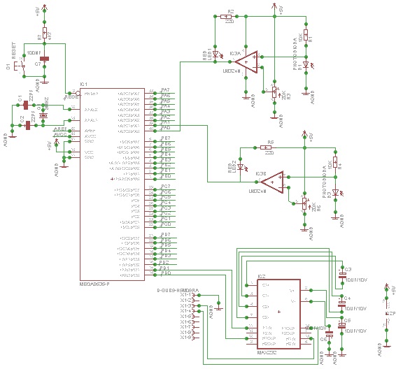
The circuit design involves the AVR-006 microcontroller interfacing with two light sensors. The sensors are connected to the microcontroller's analog input pins, specifically PINA.0 and PINA.1. These pins are configured to read the voltage levels corresponding to the light intensity detected by each sensor. The AVR-006 microcontroller is equipped with an integrated ADC (Analog-to-Digital Converter), which converts the analog signals from the sensors into digital values that can be processed by the microcontroller.
For serial communication, the microcontroller is connected to a computer via a UART (Universal Asynchronous Receiver-Transmitter) interface. This interface typically involves connecting the TX (transmit) pin of the microcontroller to the RX (receive) pin of the computer's serial port, and vice versa for the RX pin. It is also essential to configure the baud rate for communication, ensuring that both the microcontroller and the computer are set to the same speed for seamless data transmission.
The program written in C will initialize the ADC to read from the specified pins, convert the analog values to digital, and then transmit these values via the serial interface to the connected computer. The data sent can be formatted as strings, allowing the computer to interpret and display the light intensity readings effectively.
In summary, the project encompasses the hardware setup of the AVR-006 microcontroller with light sensors, the establishment of a serial communication link to a computer, and the implementation of a C program that facilitates the reading and transmission of sensor data. Proper understanding of the hardware specifications and communication protocols is crucial for successful implementation.use microcontrollers to communicate in serial between the microcontroller (AVR-006 kit) with a computer. In this project we will use microcontroller AVR-006 from Circuits-Home. Before creating the program, the first job we have to do is understand about the hardware specs. Next, I provide an example program (in C) in serial communication between the microcontroller (AVR-006 kit) with a computer. In this tutorial, AVR-006 will be used as the sender of the two light sensor data associated with PINA.
0 and PINA. 1. Here`s the program. 🔗 External reference
Related Circuits
This document provides information on the technical aspects of monitoring meteor counts through VHF radio receivers. It aims to address gaps in existing literature and offers alternative perspectives on observational techniques, supported by real data. While many online resources...
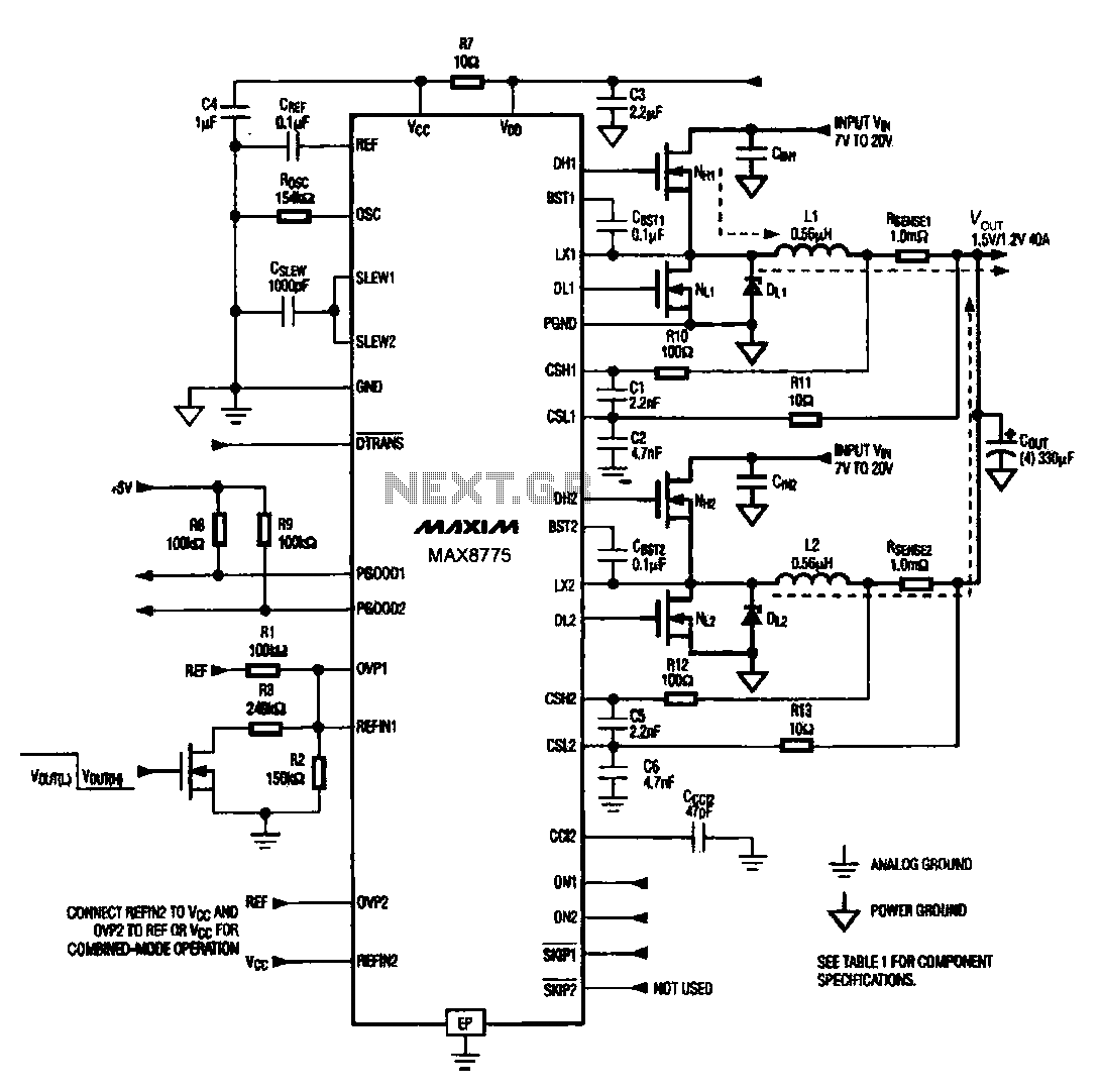
Notebook computer chip power supply circuit, which generates the PWM circuit using MAX8775. The notebook computer chip power supply circuit utilizes the MAX8775 integrated circuit to generate a Pulse Width Modulation (PWM) signal. The MAX8775 is a high-efficiency step-down voltage...
The circuit automatically powers down a computer after Windows has been shut down, preventing users from forgetting to turn off their machines. Upon shutting down Windows, a click occurs after one second, disconnecting the PC from the mains supply....
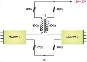
Connecting two PCs via modems using a twisted pair cable may not yield any results because the modems are designed to operate over a phone line. The scenario described involves the attempt to establish a connection between two personal computers...
This interface is needed to connect the phone to a PC, because the PC's serial port works with voltage levels between -12 and 12V (RS232 protocol) and the phone operates between 0 and 5V (TTL protocol). Don't even think...
Additional examples for connecting transceivers to a computer for SIMPLEX software operations are detailed in the pc_tx.bmp file included in the simplex.zip file. The provided information indicates that the pc_tx.bmp file contains visual representations or diagrams that illustrate various methods...