
serial ir transmitter

This circuit serves as a fundamental example of a low-power infrared transmitter, leveraging basic electronic components to achieve effective communication with infrared receivers. The design's simplicity allows for easy assembly and troubleshooting, making it suitable for beginners in electronics. The inclusion of indicator LEDs enhances the user interface by providing visual feedback on the circuit's operational status.
The choice of components, such as the 1N914 or 1N4148 diodes, serves to protect sensitive parts of the circuit from potential voltage spikes or incorrect polarity, ensuring longevity and reliability. The use of standard resistor values, along with the application of Ohm's law, facilitates the calculation of current flow through the LEDs, ensuring they operate within safe limits.
The physical layout of the circuit, with the IR LED connected via a telephone cable, allows for flexibility in positioning the transmitter relative to its receiver. This configuration is particularly useful in applications where space constraints exist or where the transmitter needs to be discreetly placed.
Overall, this circuit exemplifies fundamental principles of electronics while providing practical functionality in infrared communication, making it an excellent project for those seeking to enhance their understanding of electronic circuits and components.This is essentially the simplest circuit with additional indicator LED`s and appropriate resistor values. The dotted line is to indicate that the IR LED is separated by a length of wire (telephone cable in this case) from the rest of the circuit.
The linux infra-red daemon lircd pulls the RTS (ready-to-send) serial line positive (about +12V) as pa rt of its initialization. This circuit uses that to light a green LED indicating that the driver is loaded and basic connections are at least superficially in order. Lircd transmits IR signals as a series of 38Khz pulses on the DTR (data-terminal-ready) line. Equipment with IR receivers will pick-up the pulses from the IR LED. Humans can see the pulses from the red LED. This is a low power IR transmitter intended to be attached to the front of or very near (1-2 ft. ) the receiver box. I`ve found it very reliable in this range. Both LED`s are visible and the red flash LED easily catches the eye. If you know nothing else about electronics theory you should at least learn Ohm`s law. It easily determines the entire operation of this circuit. Note the following points: I measure the positive RTS and DTR voltage at about +11. 5V on my machine. It`s not recommended that you draw more than say 10-12mA from the serial chip. Using these values and applying Ohm`s law to the green LED: RTS and DTR may also be negative and -12Volts would likely damage the LED`s.
The 1N914 (or 1N4148) diode protects them. There should also be a diode protecting the green LED but I`ve not found this necessary with my specific hardware. 1N914 is the radio shack component number for the diode. Anything reasonable would work here and other circuits suggest 1N4148. The green and red LED`s are smaller ones from a radio shack variety pack and the IR LED was removed from an old remote control.
The 4. 7k © resistor is colored yellow/violet/red and the 3. 3k © orange/orange/red. See 🔗 External reference
Related Circuits
The FM302E-I-type FM transmitter exciter is utilized in Japan's NEC HPB a 1210 motherboard. It features direct carrier frequency modulation, phase-locked frequency stabilization, and frequency synthesis. The preamplifier (BLF-177 FET) is directly driven by an actuator, achieving a maximum...
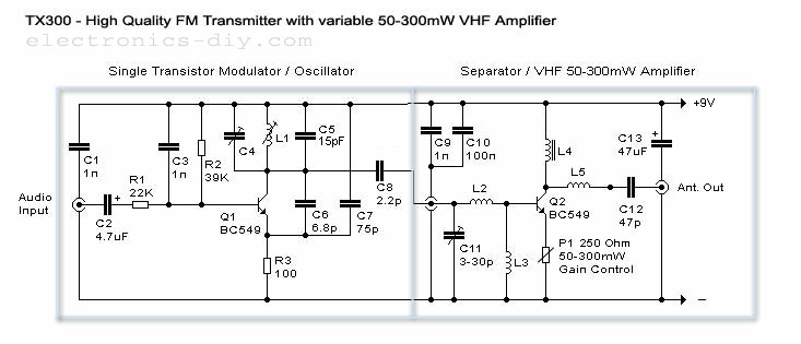
The amplifier features the same architecture as the TX500, but the TX300 is equipped with a single-stage variable VHF amplifier. This schematic is designed for those seeking a simpler alternative to the TX500, requiring fewer components. It is an...
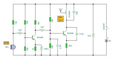
This is a mini FM transmitter circuit that utilizes two transistors. The audio sensitivity is notably high when paired with an ECM type microphone. The transmitter operates using a Hartley oscillator configuration. Typically, the capacitor in the tank circuit...
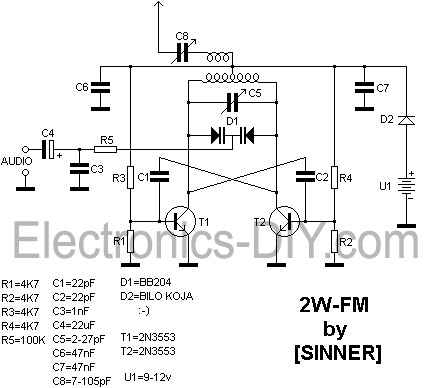
This 2 Watt FM transmitter is capable of providing a range of up to 10 kilometers under optimal weather conditions. For maximum range, a dipole antenna should be utilized. The transmitter can be tuned to frequencies between 88 and...
Building an FM radio transmitter for an iPod is straightforward. It features a power switch located at the bottom, allowing the user to turn it on and adjust their radio and transmitter to the desired frequency. A copper wire...
This is a well-designed basic FM transmitter that allows the reception of transmitted signals within a range of 1-2 km using a standard FM receiver. Additionally, the circuit features a coil mounted on the printed circuit board. The amplitude...