
Subwoofer Controller
The described circuit functions as a conventional phase control for audio applications, particularly suitable for subwoofer systems. The design employs a single operational amplifier (opamp), with a recommendation to utilize a dual opamp configuration to minimize source impedance. This is particularly beneficial when interfacing with other audio components, such as a crossover network, which may further enhance performance by allowing the omission of the initial stage if the driving source is adequately matched.
The TL072 opamp is specified due to its favorable characteristics, including low noise and sufficient bandwidth for subwoofer applications. The circuit's simplicity is a key feature, requiring no specialized components such as precision resistors or capacitors. The variable resistor, labeled VR1, serves as the phase control potentiometer, which should be of a linear taper to ensure smooth adjustment of the phase shift. The inclusion of a phase switch allows for easy selection of phase alignment, which can be critical in optimizing sound quality and coherence in multi-speaker setups.
Overall, the circuit's design reflects a straightforward approach to phase manipulation in audio systems, leveraging readily available components while ensuring compatibility with standard audio equipment. The implementation of this circuit can enhance the performance of subwoofers by allowing for precise phase adjustments, contributing to improved sound quality and listener experience.The circuit is completely conventional, and has been around almost forever in one guise or another. Similar circuits were used in the valve (tube) era, so there is nothing new about it. The circuit has already been published on these pages as a guitar tremolo circuit, but fairly obviously, that is not suitable for this purpose. The circuit uses one opamp, but a dual opamp is shown and recommended to ensure that the source impedance is low.
If driven from the output of a crossover (opamp based), the impedance will be fine, and the first stage may be omitted. There is nothing special about the circuit, and a TL072 opamp will be more than adequate for any subwoofer system. VR1 is the phase control pot, and should be linear. No special precautions or close tolerance resistors or caps are needed. The phase switch 🔗 External reference
Related Circuits
The controller is quite simple. An input buffer ensures that the input impedance of the source does not affect the integrator performance and allows summing of left and right channels without any crosstalk. The output provides a phase reversal...
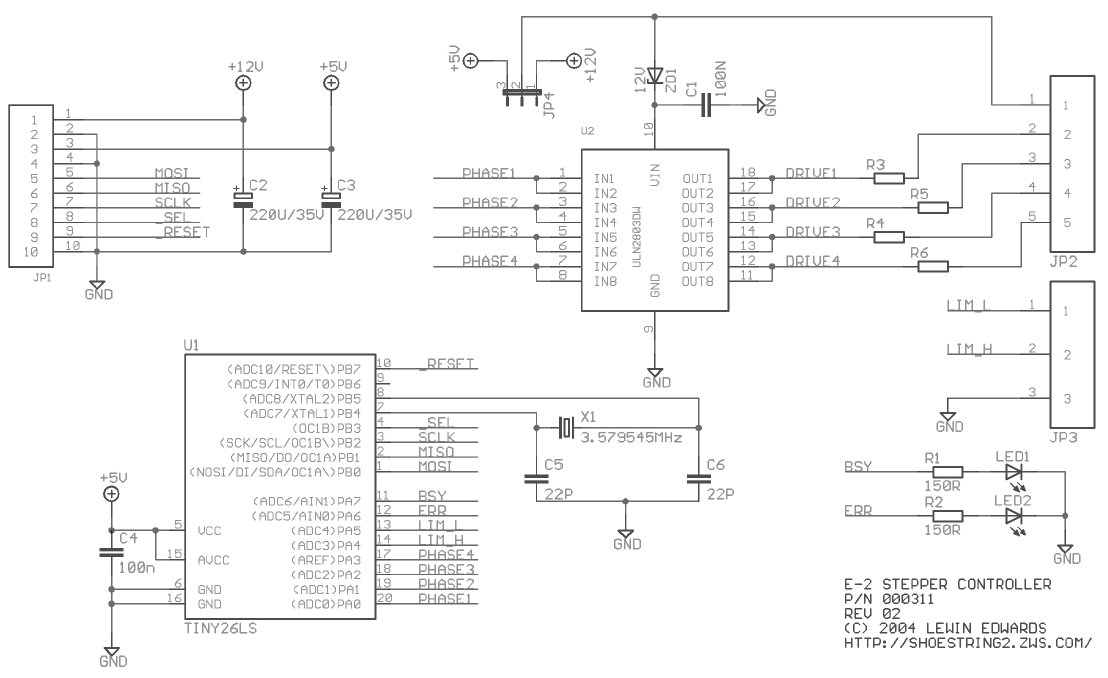
Stepper motors are beneficial for low-speed, intermediate-torque drive and positioning applications, especially where precise sub-revolution rotor position control is required. These motors are frequently utilized to drive the reels of electromechanical slot machines, position floppy disk drive heads, operate...
The fins were added to a simple flat aluminium panel, and are made from 20 x 20 x 3mm aluminium angle. Their purpose is threefold - they improve the performance of the plate as a heatsink (although this is not...
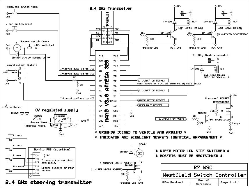
The core of the switch controller is an Arduino Nano microcontroller, which will serve as the interface between the dashboard switches, wireless steering wheel buttons, and the vehicle's lighting, indicators, windscreen wipers, and DigiDash2 GPS stopwatch. This setup facilitates...
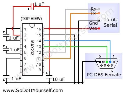
A device that provides a USB port is recognized as a "CP2103 USB to UART Bridge Controller" when connected to a Windows PC. According to the device documentation, it communicates in serial format at 38400 bps. The USB pinout...
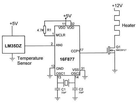
The electrical circuit diagram of this temperature control circuit consists of a 3-pin analog temperature sensor (LM35DZ), a built-in A/D converter microcontroller (PIC16F877), and the heater driver (IRL1004). The temperature control circuit utilizes the LM35DZ, a precision analog temperature sensor...