
series robot circuit
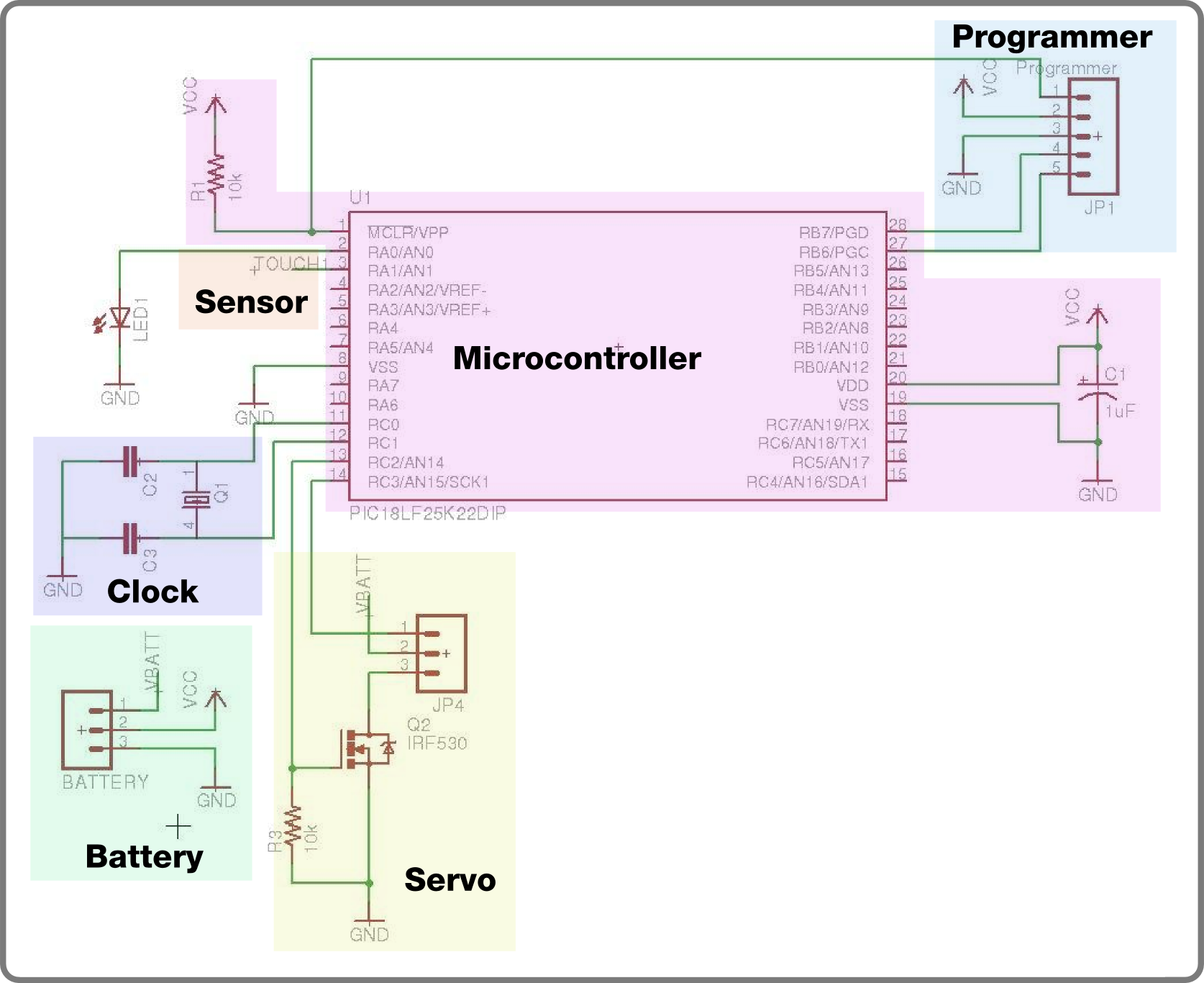
The first step involves placing a chip socket on the board, allowing for a non-permanent connection of the microcontroller. The power connection will be made using the right connection strip on the Radio Shack board, while the left will serve as the ground. Wires should be connected from Pin 20 on the chip socket and Pin 2 on the programming header to the power strip. The ground connection requires running a wire from the ground strip to Pin 3 on the programming header, and subsequently to Pin 19 on the chip socket. A reset line must also be wired to the processor for programming purposes, connecting Pin 1 on the chip socket to Pin 1 on the programming header, with a 10k resistor placed from there to power. This configuration allows the programmer to reset the microcontroller when connected, while it remains powered when disconnected.
An external oscillator will be used for timekeeping, placed between Pins 11 and 12 on the microcontroller, with a 22pF capacitor connected from each pin to ground. To indicate project status, a status LED will be added by connecting a 220-ohm resistor from Pin 2 on the chip socket to an empty row on the breadboard, followed by connecting the LED from that row to the ground strip. A 1uF capacitor will also be added between Pins 19 and 20 on the chip socket, ensuring correct orientation with the negative side to ground and the positive side to power.
Next, the microcontroller should be inserted into the chip socket, and the programmer connected to the programming header (noting that Pin 6 on the programmer is not needed). An example project should be downloaded and programmed into the microcontroller, with the expectation that the status LED will blink on and off in one-second intervals.
The circuit for controlling the servo motor will be added next. A transistor will be placed on the protoboard past the chip socket, with the servo header positioned similarly. The connections between the microcontroller and the servo include connecting Pin 13 on the microcontroller to Pin 1 (gate) on the transistor, along with a 10k resistor between Pin 1 on the transistor and ground to prevent accidental activation. Pin 3 on the transistor (source) will connect to ground, while Pin 2 (drain) will connect to Pin 3 on the servo header (ground). Finally, Pin 14 on the microcontroller will connect to Pin 1 on the servo header (signal) to control the servo's position.
The modified battery holder will be integrated next, connecting the ground wire to the ground strip, the +4.5V wire to Pin 2 on the servo header, and the 3V wire to the power strip. A reliable connection method involves looping the insulated wire through several holes on the circuit board for strain relief before soldering the ends to the perfboard.
A wire for touch sensing will be added, utilizing the microcontroller's built-in charge time measurement unit (CTMU) to detect touch. A length of wire will be connected to Pin 3 on the microcontroller, with the opposite end stripped to expose metal for touch sensing.
After verifying all connections, the servo motor can be plugged in, and the battery switched on. The status light should blink consistently, and the servo should respond to touch on the sensor wire by rotating in both directions. If successful, the project is ready for further programming and complexity in the following weeks. If issues arise, connections should be rechecked, and assistance can be sought from the project's forum. Calibration of the touch sensor may be necessary for reliable operation, with further instructions to follow.For our second build in the Make It Last Build Series, we`re constructing a robotic plant. This week, we`re going to put together the brains of the machine, which we will use in the coming weeks to bring our plant to life. This basic circuit will have support for one servo motor, an external crystal to keep accurate time, a capacitive touch inpu
t, and plenty of I/O pins to drive LEDs, and read other sensors. This time around, we`ll be soldering it together to make a more permanent design, that will be perfect for placing in your plant pot. Just getting started We suggest you take a look at the announcement post for an introduction to the project and a parts list, then follow along with these instructions to build the brains for the robot plant.
If you haven`t signed up for the newsletter, now is a good time to do so. Also, as a reminder, you don`t need to purchase any parts or build our project to be eligible for the contest in fact, the more creative you get, the better! So without further ado, lets get to the building! Note: We`re going to be soldering this project together on a perfboard. If you`ve never used them before, check out Collin`s Perfboard Prototyping video for a great introduction.
If you`re still nervous, you can certainly just build your circuit on a solderless breadboard! The first step is to place our chip socket on the board. The sockets provides a way to connect our microcontroller without making it permanent, in case we need to swap it out for some reason. For our circuit, we`ll use the connection strip on the right (labeled X` on the Radio Shack board) for power, and the one on the left for ground.
Connect wires from Pin 20 on the chip socket and Pin 2 on the programming header to the power strip. The ground connection is a bit trickier, since we need to run a wire from the left side of the board to the right side of the chip socket. Connect a wire from the ground strip to Pin 3 on the programming header, then from there to Pin 19 on the chip socket.
Next, we need to wire the reset line to the processor, so that the programmer will be able to do it`s job. Run a wire from Pin 1 on the chip socket to Pin 1 on the programming header, then place a 10k resistor from there to power.
This way, when the programmer is connected, it can overpower the resistor and reset the microcontroller, and when it is disconnected, the microcontroller will stay on. In the data logger project, we used an oscillator that was built into the microcontroller to keep time.
This was convenient because it didn`t require any extra parts, however it isn`t quite as accurate as it could be. For this project, we`ll use an external one to make sure that the plant keeps the correct time. Place the oscillator between Pins 11 and 12 on the microcontroller (it doesn`t matter which way it is inserted).
Next, place a 22pF capacitor from each of these pins to ground. Next, let`s add a status LED so that we can see if our project is working. Connect a 220 ohm resistor from Pin 2 on the chip socket to an empty row on the breadboard. Then, connect an LED from that row to the ground strip, making sure that the negative (short) lead of the LED is connected to ground. Now, add a. 1uF capacitor between Pins 19 and 20 on the chip socket. Note that for this part, orientation does matter. Make sure that the negative side is connected to ground, and the positive to power. Let`s take a break from soldering, and test that our circuit works! Stick the microcontroller into the chip socket, then connect the programmer to the programming header (note that Pin 6 on the programmer isn`t connected; it isn`t necessary for this circuit).
Download the example project from here (zipped file), give it a look over, then program it to the microcontroller. If all went well, the status LED should flash on then off in intervals of one second. The final thing we need to add to our project is a circuit to control the servo motor. Place the transistor in the protoboard just past the chip socket (leaving one row between them worked well), making sure that Pin 1 on the transistor is closest to the chip socket.
Next, place the servo header just past that, again skipping a single row between the two. Next, we need to wire up the connections between the microcontroller and the servo. There are two parts to the circuit- the transistor, which turns power to the servo on and off, and the servo header, which the servo motor plugs into. Let`s connect up the transistor first. Connect Pin 13 on the microcontroller to Pin 1 (gate) on the transistor. This connection allows the microcontroller to turn on the transistor. As a precaution, place a 10k resistor between Pin 1 on the transistor and ground. This resistor acts as a pull-down, ensuring that the transistor doesn`t accidentally turn on if the microcontroller pin is disconnected.
Next, connect a wire from Pin 3 on the transistor (source) to ground. Finally, run a wire from Pin 2 on the transistor (drain) to Pin 3 on the servo header (ground). The transistor can switch the servo off by disconnecting it`s connection to ground. Finally, run a wire from Pin 14 on the microcontroller to Pin 1 on the servo header (signal). The microcontroller will generate a command signal on this line to control the position of the servo. The next step in putting together the robot plant brains is to connect up the modified battery holder.
If you haven`t already modded yours, see the instructions in the newsletter to do so before continuing. There are three connections that need to be made here the ground (black) wire needs to be connected to the ground strip, the +4.
5v (red) wire to pin two on the servo header, and the 3v (green, or whatever color wire you used) to the power strip. You could just solder the wires in directly, however a more reliable way to make the connection is to loop the insulated wire through a few holes on the circuit board to provide some strain relief, then solder the ends to the perfboard.
You might need to make the holes a bit larger in order to fit the insulated wire through, which you can do using a drill and 1/16 ³ bit. The last step in building the robot brains is to add a wire for touch sensing. Because the PIC has a nice charge time measurement unit (CTMU) built in, it is possible to detect a human touch using some crafty programming and a single wire.
Connect a small length of wire (six inches is fine) to Pin 3 on the microcontroller. Strip a half inch of the insulation off of the opposite end of the wire, leaving a patch of metal as an exposed touch switch. Later on, we`ll connect this to a more suitable button. Now comes the moment of truth! Be sure to double-check your connections, then plug in the servo motor and switch on the battery. The status light should continue to blink on or off every second, and the servo motor should turn in one direction and then the other when the sensor wire is touched.
If everything is working, congratulations! You`re all set to add some more complex behavior to this base next week. If something isn`t working, don`t fret- double-check all of your connections, and if you can`t figure it out, head over to the forum and let us know! Also, it is possible that the touch sensor will need to be calibrated to work reliably- more on that next week.
🔗 External reference
Related Circuits
This is a simple 1.5V powered LED flasher circuit diagram. This circuit can flash 1.7V or 2.3V LEDs (depending on the color) using a 1.5V DC input. The LED will turn on when the 100µF capacitor is charged by...
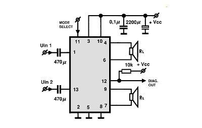
A simple Class B power amplifier can be constructed using the TDA8560 audio integrated circuit (IC). The TDA8560 amplifier features an internally fixed voltage gain, ensuring excellent channel balance. This audio amplifier project is capable of delivering dual 40-watt...
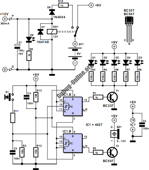
This circuit is designed to control the mains pulse. The pulser's purpose is to switch the mains voltage on and off at intervals ranging from just under one second to a maximum of ten minutes. This functionality is beneficial...
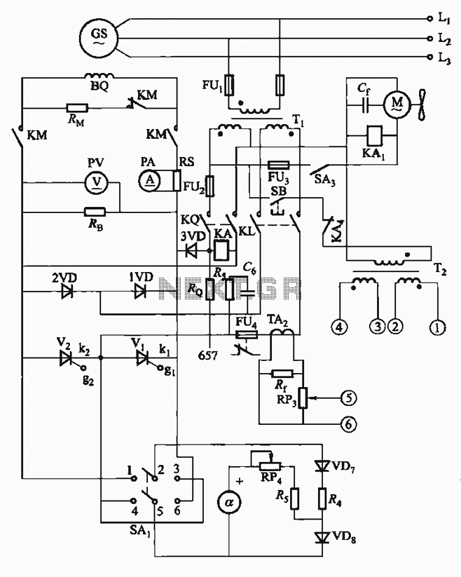
The FKL-32 type automatic thyristor excitation device is designed for synchronous generators with a terminal voltage of 400V and a capacity of 500kW or below. It is used for the automatic adjustment of excitation. The FKL-32 automatic thyristor excitation device...
Construct a low-cost and relatively simple robot that activates whenever a desk lamp is illuminated. The design does not incorporate any sensors. This robot can be designed using basic electronic components to create a simple activation mechanism based on light...
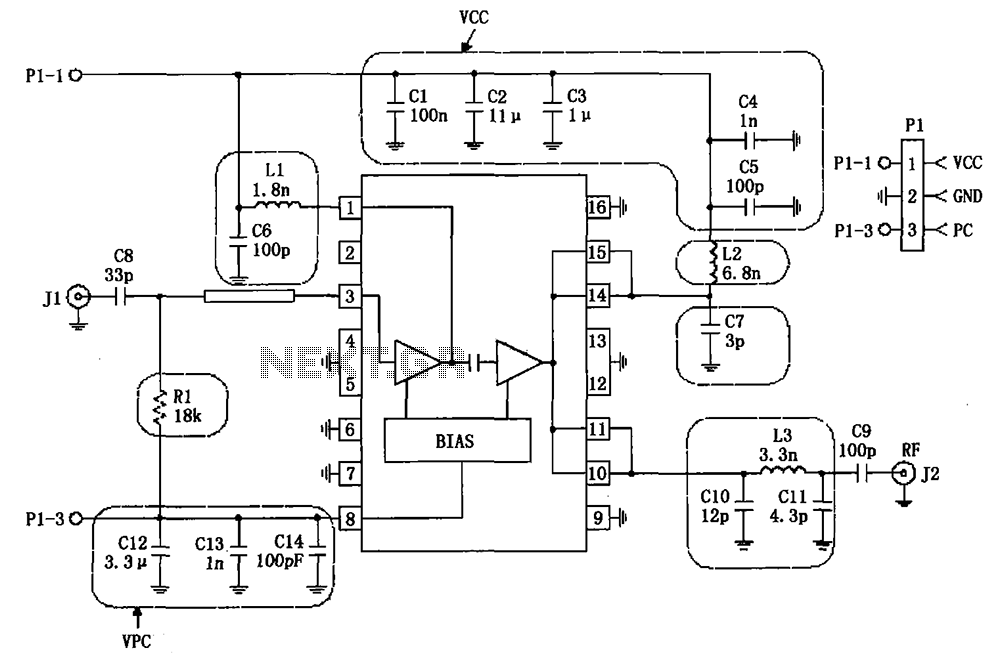
The RF2132 linear power amplifier circuit is depicted in the provided figure. A radio frequency (RF) signal enters through input pin 3 and is processed via a preamplifier. The final stage of the amplifier outputs a gain of 10....