
Servo Controller Help
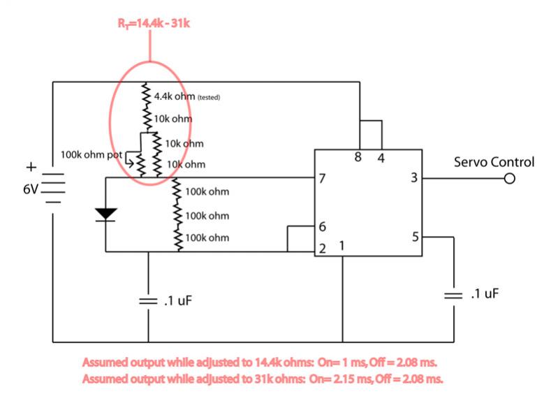
To address the issue of limited servo motion, it is essential to analyze the circuit design and parameters influencing the servo's operation. Servos typically require a control signal that varies between 1 ms to 2 ms pulse width for a full range of motion from 0 degrees to 180 degrees. If the circuit is only producing a pulse width corresponding to a 90-degree rotation, several factors may be at play.
First, verify the power supply to the servo. Servos usually operate at a specific voltage range, commonly 4.8V to 6V. Insufficient voltage can restrict the servo's range of motion. Ensure that the power supply can deliver adequate current as well, as servos may draw more current under load.
Next, inspect the pulse width modulation (PWM) signal being sent to the servo. The PWM signal should be generated by a microcontroller or a dedicated servo controller. Check the programming or configuration of the controller to ensure that it is set to produce the correct PWM frequencies and pulse widths. For example, a standard servo requires a frequency of approximately 50 Hz.
Additionally, examine the connections and components within the circuit. Loose connections, inadequate resistors, or faulty components can also impede the proper functioning of the servo. It is advisable to use an oscilloscope to visualize the PWM signal and ensure it meets the servo's specifications.
Lastly, consider the servo's mechanical constraints. If the servo is physically blocked or if the linkage system is not designed for full range motion, it may only rotate 90 degrees regardless of the input signal. Ensure that the mechanical setup allows for the desired range of motion without obstruction.
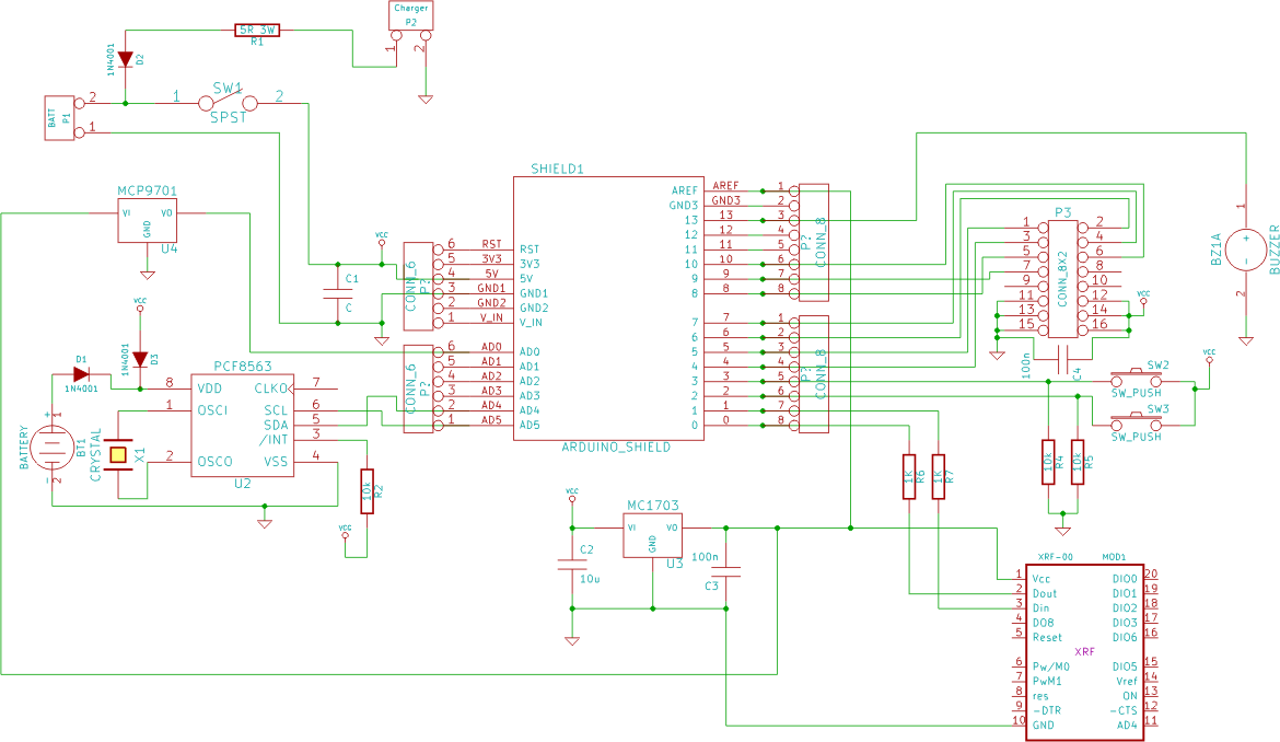
By systematically evaluating these aspects, it should be possible to diagnose and resolve the limitations in the servo's range of motion.I`m not able to get this circuit to give me full range of motion of a servo (only about 90 degrees). Maybe someone can take a look at the circuit and.. 🔗 External reference
Related Circuits
Power Saving Using Time Operated Electrical Appliance Controlling System is a reliable circuit that takes over the task of switching on/off the electrical devices with respect to time. This project replaces the manual switching. It has an inbuilt real-time...
DC Servo Motor Driver kit, designed using MC33030 IC, is the fastest and low cost way of getting your DC Servo Motor up and running. More: Input - 12 VDC Output - can drive up to 1 A Load...
If you have a servo and you want to test it but do not have a remote control or a dedicated tester, you can create a simple schematic for a servo tester. This circuit is based on a 555...
This circuit is designed to serve as a programmable LED display for various applications. It features an 8 x 32 LED dot matrix interfaced with a Xino (or Arduino). In addition to the display, the circuit includes two buttons...
This project involves an automatic room light controller with a visitor counter utilizing a microcontroller. It is a dependable circuit designed to manage room lighting while accurately counting the number of individuals present. When a person enters the room,...
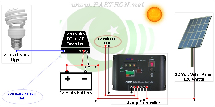
A solar charge controller is an electronic device used in solar system installations to regulate the amount of charge directed toward a battery from a solar panel. Charge controllers come in various types and ratings. The term "charge controller"...
Warning: include(partials/cookie-banner.php): Failed to open stream: Permission denied in /var/www/html/nextgr/view-circuit.php on line 713
Warning: include(): Failed opening 'partials/cookie-banner.php' for inclusion (include_path='.:/usr/share/php') in /var/www/html/nextgr/view-circuit.php on line 713