
how to test servo servo tester simple

The servo tester circuit utilizes the 555 timer IC in astable mode to generate a pulse-width modulation (PWM) signal, which is essential for controlling the position of the servo motor. The basic configuration includes a 555 timer, resistors, capacitors, and a power supply, typically ranging from 5V to 12V, depending on the specifications of the servo being tested.
The 555 timer is configured to produce a square wave output that varies in duty cycle, allowing the user to adjust the pulse width. This adjustment is achieved by modifying the resistance values of the connected potentiometer and resistors, which in turn changes the timing of the output signal. The output from the 555 timer is connected to the control wire of the servo, while the power and ground terminals are connected to the respective power supply.
For the construction, a standard 555 timer IC (such as the NE555) is used, along with two resistors and a capacitor to set the frequency and duty cycle of the output signal. A potentiometer can be included to allow for easy adjustments. The circuit is designed to be compact and can be assembled on a breadboard or a printed circuit board (PCB) for more permanent applications.
This servo tester circuit is not only effective for testing standard servos but can also be adapted for use with low-current brushless electric motors. By connecting the motor in place of the servo, the same PWM signal can be used to control the motor's speed and direction, making this circuit versatile for various applications in robotics and model control systems.If you have a servo and you wan`t to test it and you do not have a remote control to do that, or want a tester to test it you can try making the following schematic of servo tester. You can se is based on a 555 timer. The circuit is very simple and cheap to make and it will work just fine. I will post other schematics of servo testers. You can al so use this circuit to test low current brushless electric motors. 🔗 External reference
Related Circuits

This circuit is designed to test the presence of mains voltage without direct electrical contact with the mains line. The core component of this circuit is the CMOS IC CD4033, which features a five-stage decade Johnson counter and an...

The circuit features a straightforward long timing mechanism. Activating switch AN initiates the timing process, while tone PR allows for timing adjustments. The timing range spans from 3 minutes to 220 minutes. With a capacitance value of 2200 µF,...

The circuit for the RS232 serial interface exhibits mild complexity. The primary components of the circuit include the 18F4520 microcontroller, MAX233A level shifter, and a DB-9 connector. This circuit utilizes a basic +5V power regulator to supply the digital...

The circuit described here can generate three distinct US-style siren sounds: police, ambulance, and fire engine. The desired sound can be selected using switch S1. This circuit is suitable for various applications, including toys like model vehicles and alarm...

When there is a need to amplify audio signals from various sources before they reach a custom amplifier, a preamplifier (or preamp) is typically employed. This document suggests a specific circuit that is interesting due to its use of...
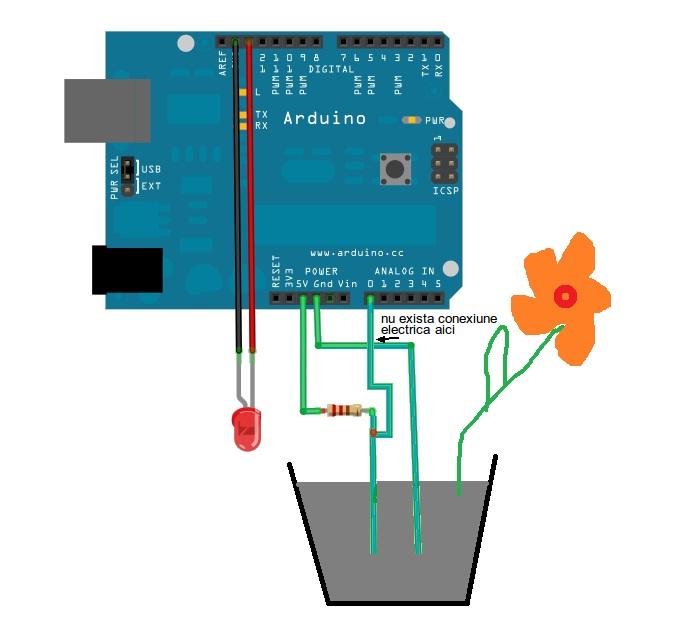
This is a simple Arduino project for a soil moisture sensor that will light up an LED at a certain moisture level. It uses the Arduino Duemilanove microcontroller. This project employs a soil moisture sensor to monitor the moisture content...
Warning: include(partials/cookie-banner.php): Failed to open stream: Permission denied in /var/www/html/nextgr/view-circuit.php on line 713
Warning: include(): Failed opening 'partials/cookie-banner.php' for inclusion (include_path='.:/usr/share/php') in /var/www/html/nextgr/view-circuit.php on line 713