
Doorbell Memory Circuit
An electronic doorbell memory circuit is designed to capture and store the signal from a doorbell when the user is unavailable to answer it. The circuit typically consists of a few key components: a doorbell switch, a microcontroller or logic circuit, a memory module, and an output display (which can be an LED or a small screen).
When the doorbell is pressed, the switch sends a signal to the microcontroller. The microcontroller is programmed to recognize this signal and subsequently activate the memory module. This module can either be a simple EEPROM (Electrically Erasable Programmable Read-Only Memory) or a more complex flash memory, depending on the requirements of the design. The memory module stores the timestamp of when the doorbell was activated, allowing the user to review the history of doorbell activations later.
For output, an LED indicator can be used to signal that a visitor has rung the doorbell while the user was away. Alternatively, a small display can be integrated to show the exact time and date of the doorbell press. In more advanced designs, the circuit may include connectivity options to send notifications to the user's smartphone via Bluetooth or Wi-Fi, enhancing the functionality by allowing remote monitoring.
Power supply for the circuit can be derived from a standard AC doorbell transformer or a battery, depending on the installation requirements. Proper circuit protection, such as fuses or diodes, should also be included to protect against voltage spikes or reverse polarity.
This design not only provides convenience but also enhances security by ensuring that users are aware of visitors even when they are not present to answer the door directly.If you re expecting an important visitor but you just have to step out for a moment, an electronic doorbell memory can come in handy so you can see whether someone rang while you were out. Of course, you can t tell whether it was the visitor you were expecting who dropped by then, but a call to the mobile phone of the person concerned can quickly answer that question.
A doorbell memory can also save you the trouble of going to the front door (if you live upstairs) when you think you heard the bell but aren t sure. And if you can t buy one, then of course you can build one yourself! Read on to find out how.. 🔗 External reference
Related Circuits
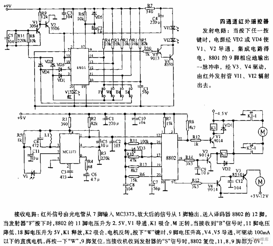
The receiving circuit involves an infrared signal being input to the MC3373 from pin 7 via a phototube. The amplified signal is output from pin 1 and sent to pin 12 of the decoder 8802. When the transmitter F...
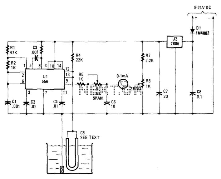
Using a capacitor sensor to detect water levels is a straightforward sensing method. This circuit employs C5, which consists of 10 to 20 inches of #22 enameled wire as one of the electrodes. The oscillator, an NE556 timer, experiences...
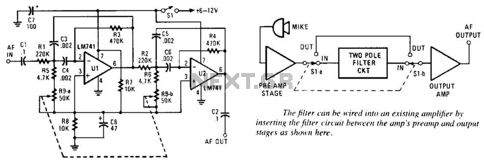
This variable-frequency audio bandpass filter is constructed using two 741 operational amplifiers (op amps) connected in cascade. Both op amps are configured as identical RC active filters, enhancing the selectivity of the overall circuit. The filter has a tuning...
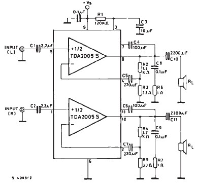
The TDA2005 car audio amplifier circuit is specifically designed for use in devices such as car radios and CD players. This amplifier circuit utilizes the TDA2005 audio integrated circuit (IC), which can deliver a maximum output power of 20...
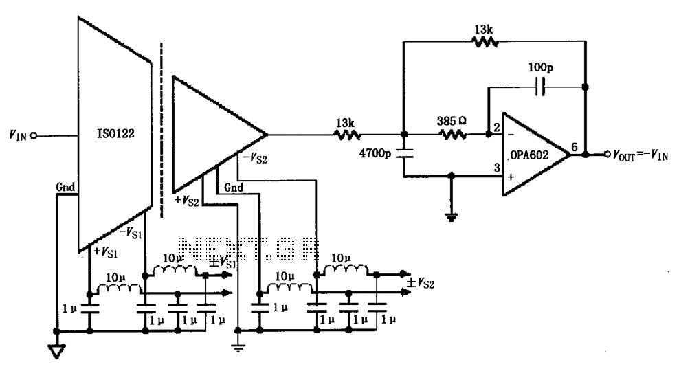
The ISO122/124-type filter circuit is designed to address noise suppression from the DC/DC converter. The internal oscillator frequency of the ISO122/124 modem is set to 500 kHz. The circuit employs inductors and capacitors for filtering to mitigate any beat...
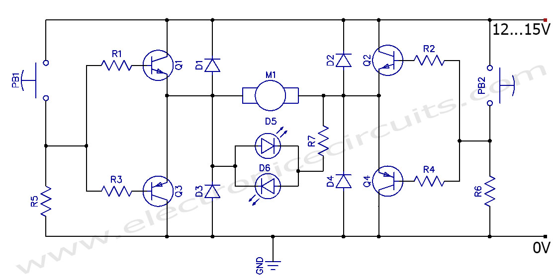
This circuit can control the direction of a DC motor, allowing it to operate in both clockwise and counterclockwise directions (forward and backward). The described circuit employs an H-bridge configuration, which is essential for reversing the polarity of the voltage...
Warning: include(partials/cookie-banner.php): Failed to open stream: Permission denied in /var/www/html/nextgr/view-circuit.php on line 713
Warning: include(): Failed opening 'partials/cookie-banner.php' for inclusion (include_path='.:/usr/share/php') in /var/www/html/nextgr/view-circuit.php on line 713