
Servo Reversers

The proposed circuit utilizes the CD4001 NOR gate as the primary component for reversing the servo direction. The NOR gate is a versatile digital logic gate that outputs a low signal when any of its inputs are high. By configuring the NOR gate in a specific arrangement, it can effectively control the polarity of the signal sent to the servo motor, thus reversing its direction of rotation.
The four resistors in the circuit serve multiple purposes, including biasing the inputs of the NOR gate and setting the voltage levels for proper operation. The values of these resistors can be selected based on the desired response time and sensitivity of the servo control. Typically, resistor values in the range of 1kΩ to 10kΩ are suitable for this application.
The three capacitors are employed to filter noise and stabilize the voltage levels in the circuit. They can also be used to create timing delays, influencing how quickly the servo responds to input changes. Capacitor values may vary, but common choices include 10µF for bulk capacitance and smaller values such as 0.1µF for high-frequency noise filtering.
The variable potentiometer is a crucial component that allows for manual adjustment of the input signal. By varying the resistance, the user can control the threshold at which the servo reverses direction. This feature adds versatility to the circuit, enabling it to be tailored to specific applications.
The overall design emphasizes simplicity and cost-effectiveness, making it accessible for hobbyists and those looking to experiment with servo control systems. The schematic diagram, which should be referenced for precise connections and component placement, illustrates how these components are interconnected to achieve the desired functionality. Proper assembly and testing of the circuit will ensure reliable operation of the servo reverser.This projects will describe a simple Servo Reverser that can be cheaply built using a CD4001 NOR gate, 4 resistors, 3 capacitors and one variable potentiometer (see schematic below). 🔗 External reference
Related Circuits
This document explains how to utilize an Arduino to control up to 12 servos simultaneously with minimal jitter. A straightforward serial interface allows for the control of the position of these 12 servo channels. Additionally, it is possible to...
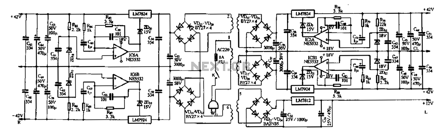
The F9500 serves as the power supply in the United amplifier circuit preamplifier. It utilizes an LM7824 and LM7924 configuration to create a 42V servo regulator power supply, incorporating the NE5532 operational amplifier for the servo circuit. In this...
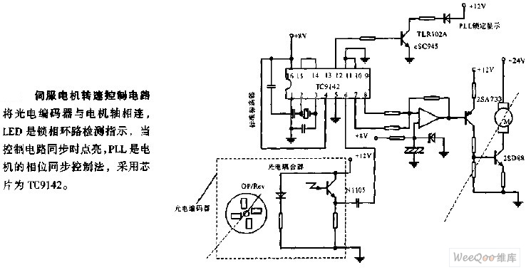
The servo motor speed control circuit connects the photoelectric encoder to the motor shaft. The LED serves as an indicator light for the phase-locked loop (PLL) detection, illuminating when the control circuit is synchronized. The PLL employs a phase...
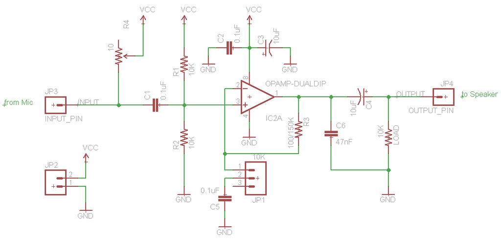
The TL072 operational amplifier is used to amplify an audio signal that is directed to both speakers and an Arduino's analog input. The amplifier is powered by a 12V, 2A wall wart, which is also regulated down to 5V...
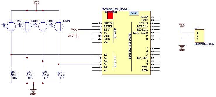
The movement of the servo is determined by the output values of the photoresistors. The impedance of these sensors changes with the amount of light incident upon them. The servo's position shifts towards the sensor that detects less light....
A modified version of the previous program allows control of multiple servomotors, utilizing all available I/O lines on port B. The following listing demonstrates the control of two servos similarly to how a single servo was managed in the...