
Telephone Line Tester Circuit
The telephone line tester is designed to provide a straightforward method for verifying the operational status of a telephone line. The core component of the tester is a voltmeter, which is calibrated to display the voltage levels present on the line. The circuit includes three resistors arranged to form a voltage divider, with one resistor being adjustable to allow for calibration of the meter reading based on the specific characteristics of the telephone line.
The modular telephone connector enables easy interfacing with standard telephone lines, ensuring that the tester can be used with a variety of telephone systems. The pushbutton switch serves to activate the measurement process, allowing the user to obtain a reading only when desired. This feature helps conserve battery life if the tester is powered by a battery.
When the tester is connected to the telephone line and the pushbutton is pressed, the meter should indicate a voltage between 5 and 10 V. A reading within this range confirms that the line is operational and capable of carrying a signal. If the voltage is significantly lower or absent, it suggests a fault in the line, which may require further investigation or repair.
Overall, the telephone line tester is a practical tool for technicians and engineers, providing a quick and reliable means of assessing the status of telephone lines in various environments. The simplicity of its design allows for ease of use while delivering accurate voltage measurements essential for troubleshooting telephone systems. The telephone-line tester consists of nothing more than a meter (that`s used to measure line voltage in the on- and off-hook state), three resistors (one of which is variable), a pushbutton switch, and a modular telephone connector. When the circuit is connected to the telephone line, a meter reading of 5 to 10 V (when SI is pressed) indicates that the line is okay. 🔗 External reference
Related Circuits
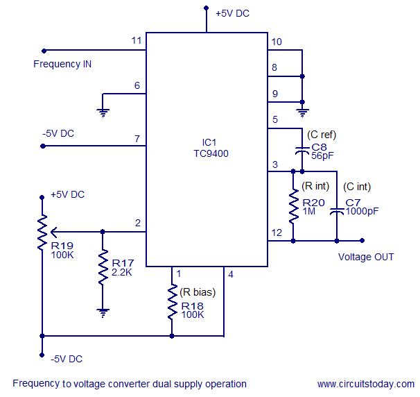
A simple frequency to voltage converter circuit designed around the TC9400 F to V / V to F converter IC. Dual and single supply versions are provided. The TC9400 is a versatile integrated circuit that converts frequency signals into corresponding...

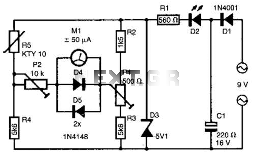
With this simple measuring device can: Determine the Zener voltage up to 25V. The connections of cathode and anode of each diode finding. Check if a diode fails. Silicon, germanium and Schottky diodes distinguish. LED test and the V...
An FM transmitter, commonly referred to as an FM transmitter, utilizes two transistors, specifically the 2N2222 model. When in operation, this FM transmitter requires a 9-volt battery for power and operates with an antenna that is less than 12...
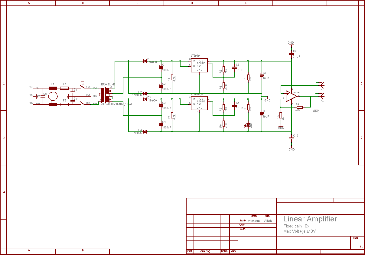
The aim of this project was to develop a linear analogue amplifier designed for laboratory use. This amplifier has to realise a voltage amplification of 10x and is intended to amplify function generator signals for tests. Power supply requirements:...

This circuit is designed as a warning flasher to alert road users to dangerous situations in low-light conditions. It can also function as a bicycle light, subject to applicable traffic regulations. White LEDs are recommended for use as a...

The circuit illustrated in Figure 4 is an AC timing circuit designed to operate for 4 hours. It utilizes the BH4024, a 7-stage serial binary counter/divider, in conjunction with a 555 timer circuit. The circuit is activated by a...