
Servoelectric Guitar Project

The Milwaukee Guitar system employs a sophisticated architecture that integrates digital control with analog signal processing to achieve precise tuning of the instrument. The core of the system is a desktop PC that acts as the central processing unit, interfacing with a USB number pad for user input. This setup allows musicians to input commands easily, which are then translated into control signals for the servomotors responsible for adjusting the tension of the guitar strings.
The Velleman K8055 USB experiment interface board serves as a crucial link between the computer and the servo circuits. This board's eight digital outputs are utilized to send binary signals to the servomotors, enabling them to move to specific positions based on the desired string tension. The two analog outputs are critical for generating the necessary control voltages for the sample and hold circuit.
The design of the sample and hold circuit is key to producing the three distinct analog voltages required for tuning. The CMOS CD4066 quad bilateral switch allows for the routing of signals with minimal distortion, ensuring that the integrity of the control voltages is maintained. The LF353 operational amplifiers, known for their high input impedance, provide the necessary buffering and amplification, ensuring that the signals are robust enough to drive the servomotors effectively.
The software component, developed in Borland C, allows for real-time control and tuning of the guitar. The program's design accommodates the tuning of individual strings, providing musicians with the flexibility to customize their tuning preferences. The arbitrary mapping of keyboard keys to specific string tensions enables a user-friendly interface, allowing for intuitive control over the tuning process.
Overall, the Milwaukee Guitar system represents an innovative fusion of digital electronics and traditional musical instruments, leveraging advanced technology to enhance the musician's experience.The current Milwaukee Guitar design uses an off-board computer (a desktop PC) to control the servomotors. A standard USB number pad is connected to the computer which then provides output signals through a Velleman K8055 USB experiment interface board to the servo circuits.
This K8055 board provides eight digital outputs and two analog outputs. In order to get three analog voltages, a sample and hold circuit using a CMOS CD4066 quad bilateral switch and two LF 353 high input impedance operational amplifiers was constructed. (schematic) The KE 8055 was controlled with C program written in Borland C (available free from Borland ) executing in the command window on a Microsoft Windows operating system.
The program permits tuning of the guitar one string at a time and provides an arbitrary mapping of keys of the keyboard to combinations of string tensions. 🔗 External reference
Related Circuits
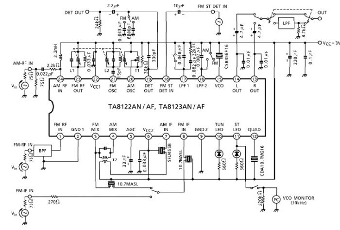
A simple low-power AM/FM radio receiver electronic project can be designed using the TA8122 integrated AM/FM receiver, manufactured by Toshiba Semiconductor. This radio receiver circuit is suitable for portable radio applications and similar devices. The TA8122 radio receiver circuit...
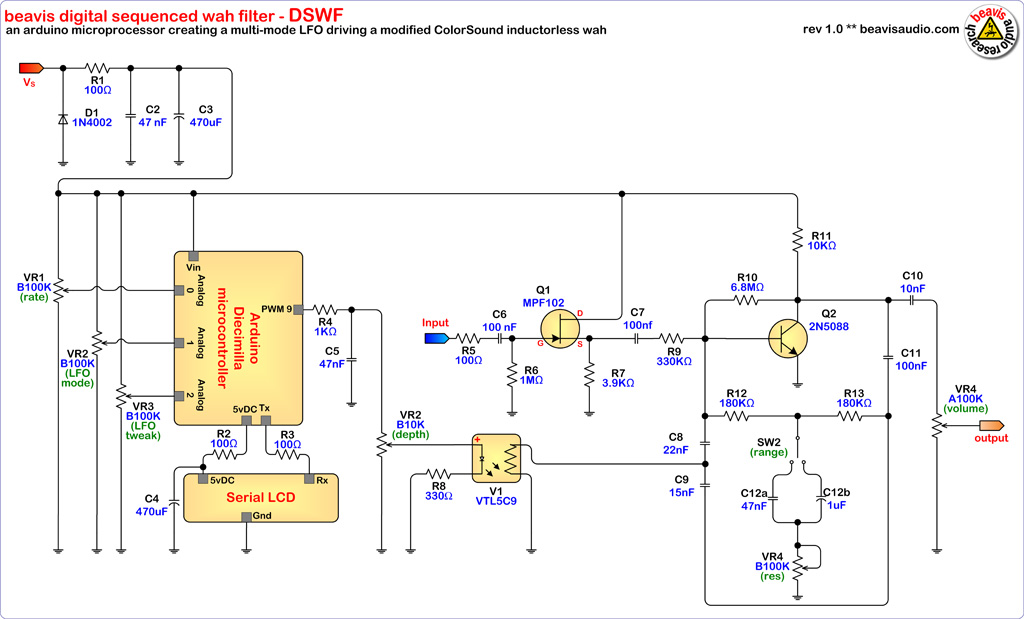
The microcontroller (MCU) is responsible for sending variable voltages over time, similar to a traditional Low-Frequency Oscillator (LFO), to an effect that can be modulated by voltage or a potentiometer on a conventional analog effect that can be replaced...
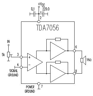
This TDA7056 power audio amplifier circuit diagram project is designed to deliver a maximum output power of 1 watt into an 8-ohm load when powered by a 6-volt supply, or a maximum output power of 3 watts into a...
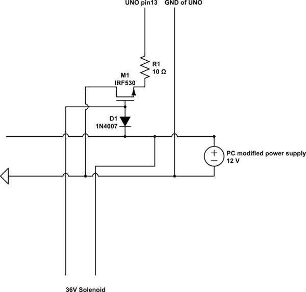
A 9 V DC battery initially powered the solenoid valve effectively. However, the solenoid did not generate sufficient force due to inadequate DC power. A modification was made to use a computer power supply as the power source. Providing...

This preamplifier is designed as a portable unit, ideal for amplifying signals generated by guitar pickups, particularly the "bug" types used with acoustic instruments. It can be utilized with any type of device and pickup. The unit features a...
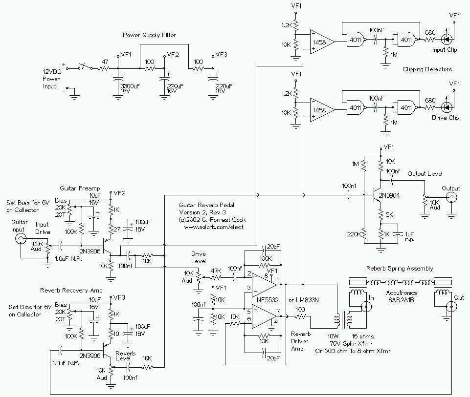
This is my second-generation guitar reverb circuit. The fidelity is much improved over the earlier design, it is suitable for use as a front-end to a guitar amplifier. This circuit features clipping indicators on the preamp and reverb recovery...