
project DSWF

To implement this design, the MCU serves as the central processing unit, controlling the voltage output that modulates the analog effect. The programming environment allows for the coding of the LFO behavior, where parameters such as frequency and depth can be adjusted in real time using physical controls. The use of ADCs enables the MCU to read the voltage levels from various input devices, facilitating user interaction.
For the voltage output, PWM is utilized to simulate an analog voltage. This technique involves rapidly switching the output pin between high and low states, where the ratio of the time spent in the high state versus the low state determines the average voltage output. By adjusting the duty cycle of the PWM signal, the MCU can effectively create a range of voltages that can be interpreted by the connected analog effect.
The schematic design would include the MCU connected to the necessary power supply, typically 5V DC, and interfacing components such as potentiometers and switches. The potentiometers would be wired as voltage dividers, with their outputs connected to the ADC inputs of the MCU. The PWM output pin would connect to the control input of the analog effect or to the optoisolator/vactrol, allowing for modulation of the effect based on the programmed LFO parameters.
In summary, the described circuit leverages the capabilities of the MCU to create an interactive and versatile LFO effect, utilizing both digital programming and analog interfacing techniques to achieve a wide range of sound modulation possibilities.The microcontroller (MCU) is responsible for sending variable voltages over time (just like a traditional LFO) to an effect that can be modulated by a voltage, or a pot on a traditional analog effect that can be replaced with an optoisolator/vactrol. Here`s a block diagram: On the left, we write some code that tells the MCU to output voltages base d on program variables. We also have the MCU read various pots and switches connected to it. This gives us real-time control over the parameters of our LFO program. Once the program is ready, we upload it to the MCU. If it compiles and executes properly, we are ready to move on to the next step. If not, we go back to the computer and debug the problem. The MCU then sends a series of voltages to the input of the analog effect. We can do this directly with a Control Voltage, or have the MCU drive an optoisolator/vactrol to act as a potentiometer. An Important Note: If you are new to MCUs, you may get the impression that a laptop or desktop computer always has to be part of the equation.
In other words, you couldn`t make a real effect pedal because you`d always have to cart around your laptop. Not true! The computer is where you write, test, and fine-tune your code. Once you have downloaded the code to the MCU, you can disconnect the laptop, stick the MCU in an enclosure along with the traditional jacks and switches, and never have to reconnect the computer.
Even if the MCU loses power, it will retain its programming. Since I already had a basic knowledge of programming the Arduino microcontroller, choosing that for the LFO engine was simple. I have a few Arduino boards in the parts bin, so away we go. Here are some of the basic things about the Arduino that make it a very nice fit with this project: Open Source: Unlike closed proprietary systems, the Arduino is open-source.
You aren`t locked into a single vendor or technology. There are tons of industry standard parts you can interface with, and at least four different sources for Arduino or Arduino-compatible boards. Remember the design goal of "Real-time user control over various parameters" Well in a traditional computer application, you`d have a screen and a keyboard and a mouse, and interact with the program and computer through things like menus and scrollbars, and the like.
But we want a hardware-based interface. So we want to set parameters with the things we like to see on stompboxes: pots and switches. Fortunately, MCUs make this incredibly simple. Our MCU has a set of analog-to-digital converters (ADCs). They sample an analog voltage and turn it into a digital value that our program can then read. Pots are easy too. You simply wire the pot up as a voltage divider and have its output go to one of the ADCs on the MCU. As you turn the pot, you vary the voltage going into the ADC, and your program simply reads that value: To implement a voltage divider with Arduino, connect lug 1 to ground, lug two to one of the analog inputs, and lug 3 to the 5 VDC+ pin.
Then use a single simple line of code to read the current value, as shown in the Code sample. The combination of devices is endless. You could replace pots with light-dependent resistors, or a joystick, or an ultrasonic range-finder. Similarly, switches could be replaced with other controllers, or even interfaces to other MCUs or computers. That`s one of the beauties of using an MCU-there are lots of easy ways to interface with the physical world.
In order to create a workable LFO, one of the key requirements is: I need to have the MCU send out a continuously variable voltage that varies over time. But the MCU is traditionally a binary/digital device. It doesn`t natively support a continuously variable analog range, like voltage. So I`m sunk right The Arduino, along with most MCUs, allows you to output a variable voltage. It accomplishes this through the use of Pulse Width Modulation. I would be crazy to try to expl 🔗 External reference
Related Circuits
The drawings and photos below are for an operating incline railway that was built by the London Model Railroad Group for its O scale model railway club located at London, Ontario, Canada. This is a single car model loosely...
In the production of LCD projectors, the primary factor threatening the lifespan of the LCD screen is the temperature generated by halogen lamps. The multi-function controller designed by this circuit is highly effective for protecting liquid crystal projectors. The...
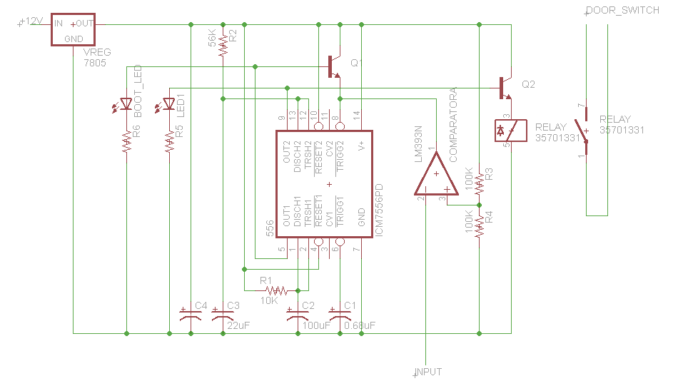
This button, with some modifications, allows the opening of an office door using Nexus One, iPhone, or SMS. Positioned near the reception desk, this button activates an electronic latch on the front door. Upon removing the assembly from the...
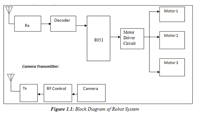
A prototype model of an agriculture-based robot has been developed to address the challenges faced by farmers who have traditionally relied on manual labor for cultivating their lands. The increasing urbanization has led to a shortage of labor, as...
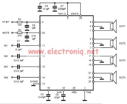
The input capacitor is used for low-frequency cut-off, with a standard value of 0.1 µF, resulting in a cut-off frequency of approximately 16 Hz. The input capacitor plays a crucial role in filtering unwanted low-frequency signals in electronic circuits. By...
Every innovation begins with a simple everyday problem, such as watching an IPL match on TV when suddenly the power goes out, prompting the search for an alternative way to watch via mobile network. Similarly, a frequent issue of...