
SF04E emission circuit diagram composed SF04B
The SF04E and SF04B remote control transmitter circuits are designed for efficient wireless communication. The SF04E transmitter operates by emitting signals that can be received by the SJ04H matching circuit. This configuration allows for seamless transmission and reception of control signals over a specified range.
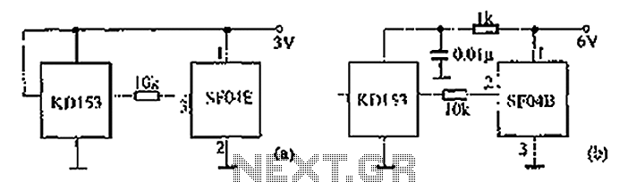
In part (A), the SF04E transmitter is detailed, highlighting its key components such as the oscillator circuit, modulator, and the antenna. The oscillator generates a carrier frequency, which is modulated by the input control signal. The modulated signal is then transmitted through the antenna, ensuring effective signal propagation.
Part (B) focuses on the SF04B transmitter circuit, which integrates the SJ04E receiving circuit. This receiving circuit is designed to capture the signals emitted by the SF04E transmitter. Key components of the SJ04E include the demodulator, which processes the incoming modulated signals, and the output stage that translates these signals into actionable commands.
Both circuits are crucial for enabling remote control functionalities in various applications, including consumer electronics and automation systems. The design emphasizes compatibility between the transmitter and receiver, ensuring reliable performance and ease of assembly. The overall schematic illustrates the necessary connections and component placements, providing a clear guide for implementation in practical scenarios. As shown in the circuit diagram SF04E emission and SF04B thereof. (A) shows a remote control transmitter SF04E composition, and it receives the matching circuit can SJ04H assem bly. (B) shows the remote control transmitter circuit consists SF04B composed by SJ04E its composition matching receive circuit.
Related Circuits

The LM35 from National Semiconductor is a precision centigrade temperature sensor that provides an analog output voltage. It operates within a temperature range of -55°C to +150°C and has an accuracy of ±0.5°C. The output voltage corresponds to 10mV...
A simple whole house FM transmitter circuit diagram and description. Operating power is a 1.5V battery of any type. This circuit is able to transmit at a distance of 30 meters. The whole house FM transmitter circuit operates on a...

This project was a surprise as the BC547 transistor (equivalent to 2N2222) can be used to construct a 500mW linear amplifier that operates across the entire HF band with excellent spectral purity and without the need for neutralization. The...
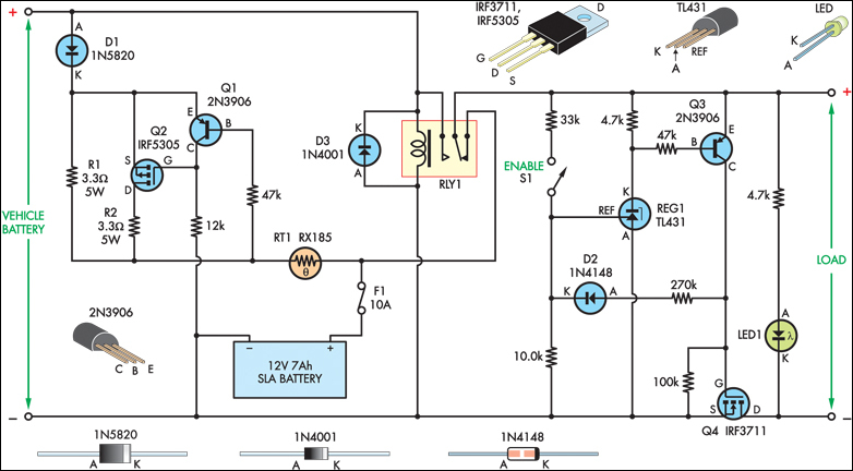
The SLA battery is charged from the vehicle's battery. When the engine is running, the voltage remains fairly constant, which greatly simplifies the charging circuit. If the SLA battery is fully charged, any further charging current from the vehicle...

A broadband high-frequency amplifying circuit is primarily composed of a high-frequency matching transformer and an amplifying transistor. This circuit is designed to handle large high-frequency signals. The input of the amplifier circuit utilizes a matching transformer to ensure that...
The following diagram is the circuit diagram of a 20W power amplifier built using the tube component EL34. The EL34 is a well-known tube, ideal for power tube amplifiers. The circuit presented is a complete design that includes both...
Warning: include(partials/cookie-banner.php): Failed to open stream: Permission denied in /var/www/html/nextgr/view-circuit.php on line 713
Warning: include(): Failed opening 'partials/cookie-banner.php' for inclusion (include_path='.:/usr/share/php') in /var/www/html/nextgr/view-circuit.php on line 713