
Gentleman AM50 amplifier circuit
The circuit is designed to optimize audio performance through its carefully structured components and configurations. The use of all-discrete components ensures minimal interference and high fidelity in sound reproduction. The twin tube K389 in the input stage provides low noise and high gain, essential for capturing the nuances in audio signals. The symmetrical complementary design allows for balanced amplification, reducing distortion and improving overall sound quality. The push-pull configuration in the output stage enhances efficiency by allowing each FET to operate in its optimal range, thereby reducing power loss and heat generation.
Capacitive coupling between stages is critical for maintaining signal integrity while preventing DC offset issues. The choice of polypropylene capacitors is significant, as they offer low dielectric absorption and high stability, contributing to the preservation of audio quality. The separate power supplies for each stage prevent interaction between them, ensuring that fluctuations in one stage do not affect another, which is vital for maintaining consistent performance.
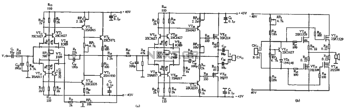
The Gm control technology implemented in the amplifier allows for precise volume adjustments without compromising the input impedance or introducing unwanted noise. This innovative approach to volume control enhances user experience while maintaining sound quality. The design reflects a comprehensive understanding of audio amplification principles, combining advanced technology with practical considerations for optimal performance in high-fidelity audio applications.The unique circuit design, technology and reasonable structure, all-discrete components, Class A FET output. As shown in Figure 2-31 below. Full circuit consists of an input stage, an output stage and power level to promote and Gm volume control circuit.
FET input stage by a twin tube K389, consisting of 09 children symmetry complementary double differential circuits and transistors with common source emitting circuit altogether. After a two-stage push-pull amplification after symmetrical complementary input voltage amplification stage.
RP3 can adjust the output tube VTs, VT6 working in state o Group A voltage amplifier stage and the input stage uses the same circuit configuration, but its output stage uses a pair of FET 2SK214 and 2SJ77 projections 7] regulating arsenic can be output tube VT32, VT33 quiescent current adjusted CPI working state. The third part is the power output stage, which includes the output bias circuit and two pairs of parallel complementary push-pull output FET channel.
And to promote inter-stage amplifier output stage using capacitive coupling, coupling capacitors Promise of capacitors polypropylene (lw (P capacitance). The coupling capacitance guarantees high quality pure o sound input level, output level and power level to promote at all levels, respectively a separate power supply to ensure that the work independently of each other between levels.
input level and promote the use of higher-level supply voltage, to ensure its large dynamic and high efficiency. the output stage voltage amplifier stage and does not have a large negative feedback loop can reduce transient distortion circuit, to improve the sound quality of a given effect.
the input stage set up large negative feedback loop (RP4, R23) is used to control the volume of the amplifier, called cross- guide (Gm) control technology it is the usual negative feedback Tuen Mun Road except that, using an adjustable potentiometer and the potentiometer slide arm ground. we know that there are two conventional volume adjustment methods, one is the input of the amplifier plus end-to-ground potential, by the partial pressure of the ground to control the input signal voltage slide arm (flat) to achieve volume adjustment.
another point is the use of an external DC potential level of resistance by changing the circuit to control the volume output ., the DC volume control clearly, the former regulated process will cause changes in the input impedance of the circuit can not work in the steady state optimum input, and a sliding noise will be amplified; the latter, although no above drawbacks, but required lc to achieve its cost, performance are to be considered while control technique has the advantage of both the above that fall.
Related Circuits
This circuit is primarily designed to provide a microphone input for standard home stereo amplifiers. Utilizing a battery supply minimizes the risk of low-frequency hum interference from mains power, simplifying the connection to the amplifier by eliminating the need...
S1 and S2 are normally open, push-to-close, momentary switches. The diodes can be either red or green and are used solely for indicating direction. The TIP31 transistors may need to be adjusted based on the motor specifications. It is...
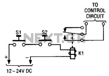
The simple two-hand safety control switch consists of two pushbutton switches connected in series; both must be depressed to energize the relay. The two-hand safety control switch is designed to enhance safety in applications where the operation of machinery or...
This circuit is an enhanced Hartley oscillator, which allows for frequency adjustment within a specified range by altering the base current. The output signal amplitude exceeds 6V when tested with a 6kΩ load resistance, making it suitable for use...
An RF power amplifier is a type of electronic amplifier used to convert a low-power radio-frequency signal into a larger signal of significant power, typically for driving the antenna of a transmitter. It is optimized for high efficiency, high...
This document provides a guide on understanding a simple computer system and its operation. It will examine the BASIC programming language and its statements, enabling communication with external circuitry. The document will also explore how to interface electronic circuits...