
SH-123 ASIC holiday lights
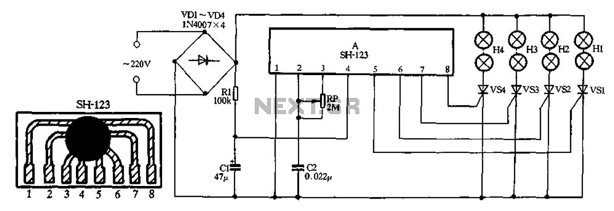
The circuit begins with the 220V AC input, which is directed to a bridge rectifier formed by diodes VD1 through VD4. This configuration converts the alternating current (AC) into direct current (DC), ensuring a consistent voltage supply for the subsequent components. The output from the rectifier is then smoothed by filter capacitor C1, which reduces voltage ripple and provides a more stable DC voltage.
Resistor R1 serves as a current limiting component, ensuring that the current flowing to the lights H1 to H4 does not exceed safe operating levels, thereby protecting the LEDs or bulbs from potential damage. The four outputs, LI to L4, are designed to control the operation of the lights in a sequential manner. This can be achieved using a microcontroller or a simple relay-based control circuit, allowing for the lights to be turned on and off in a programmed sequence.
The use of potentiometer RP allows for user adjustment of the flow rate, which in turn affects the timing of the lights' operation. By varying the resistance of RP, the duration for which each light remains on or off can be modified, creating different visual effects that simulate the excitement of a horse racing event. This feature adds an element of interactivity to the circuit, as users can customize the speed and behavior of the light sequence according to their preferences.
Overall, this circuit design provides an effective means of creating dynamic lighting effects suitable for entertainment applications, combining basic electronic components to achieve a visually appealing output.220V AC by VD1-VD4 bridge rectifier, all the way to supply four lights Hl - H4 electricity, another pass resistance Rl buck limit, filter capacitor C1 supply manifold A electri city. Manifold 4 outputs LI-L4 direct drive controllable VSl ~ VS4 sequentially turned on and off so that the lights were lit H1 ~ H4 light, forming a sense of movement in Happy Valley. Adjust potentiometer R P resistance can change four lights H1 ~ H4 flow rate of horse racing.
Related Circuits
This simple and inexpensive circuit is not limited to Christmas use. It consists of two resistors, a small-signal transistor such as a BC547, and a flashing LED. The circuit operates by utilizing a small-signal transistor, which acts as a switch...
This circuit serves as a decorative element or indicator, featuring adjustable flashing or dancing speeds of LEDs and the ability to create various light patterns. It consists of two astable multivibrators: one formed by transistors T1 and T2, and...
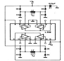
This circuit illustrates a basic configuration for driving a bipolar stepper motor using either an L293 or an L298N driver. It demonstrates that a single device can control a two-phase bipolar stepper motor. The circuit employs either the L293 or...

Family karaoke lighting design incorporates various methods for circuit control. The control circuit described here features a four-way light output with loop jumping and speed control capabilities. A microphone detects the acoustic signal strength, allowing the lights to jump...
This device is a simple timer that keeps the headlights of a vehicle illuminated for approximately 1 minute and 30 seconds. This feature is particularly useful when accessing dark areas, eliminating the need to return to manually switch off...
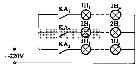
The relay control system utilizes multiple pairs of contacts, allowing for the connection of higher power lamps in parallel. The circuit design is straightforward; by altering the capacitance of the capacitor, different flashing frequencies can be achieved. The described circuit...