
L293 Basic Bipolar Stepper Motor Driver Configuration Circuit
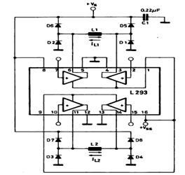
The circuit employs either the L293 or L298N integrated circuit, both of which are designed for driving motors and can handle bi-directional control of the stepper motor phases. The bipolar stepper motor consists of two coils that need to be energized in a specific sequence to achieve rotation. The L293 and L298N drivers facilitate this by providing the necessary current and voltage levels to the motor coils.
In this configuration, the control signals are typically generated by a microcontroller, which sends pulse-width modulation (PWM) signals to the driver IC. The driver IC interprets these signals and activates the appropriate outputs to energize the motor coils in the correct order. This is crucial for creating the magnetic fields that cause the motor to step forward or backward.
The L293 driver can handle up to 600 mA per channel, making it suitable for smaller stepper motors, while the L298N can handle up to 2 A per channel, allowing it to drive larger motors. Both devices include built-in diodes for flyback protection, which is essential for preventing voltage spikes generated by the inductive loads of the motor coils from damaging the driver circuitry.
For optimal performance, it is important to ensure that the power supply voltage is within the specifications of the chosen driver and motor. Additionally, proper heat dissipation measures should be implemented, especially when using the L298N, as it can generate significant heat during operation.
Overall, this circuit configuration provides a straightforward and effective means of controlling a bipolar stepper motor, suitable for various applications in robotics, automation, and other fields requiring precise motor control.The herein circuit shows basic configuration for bipolar stepper motor driving which can be applied using either an L293 or an L298N. This circuit shows that a single device can be used to drive a two phase bipolar stepper motor 🔗 External reference
Related Circuits
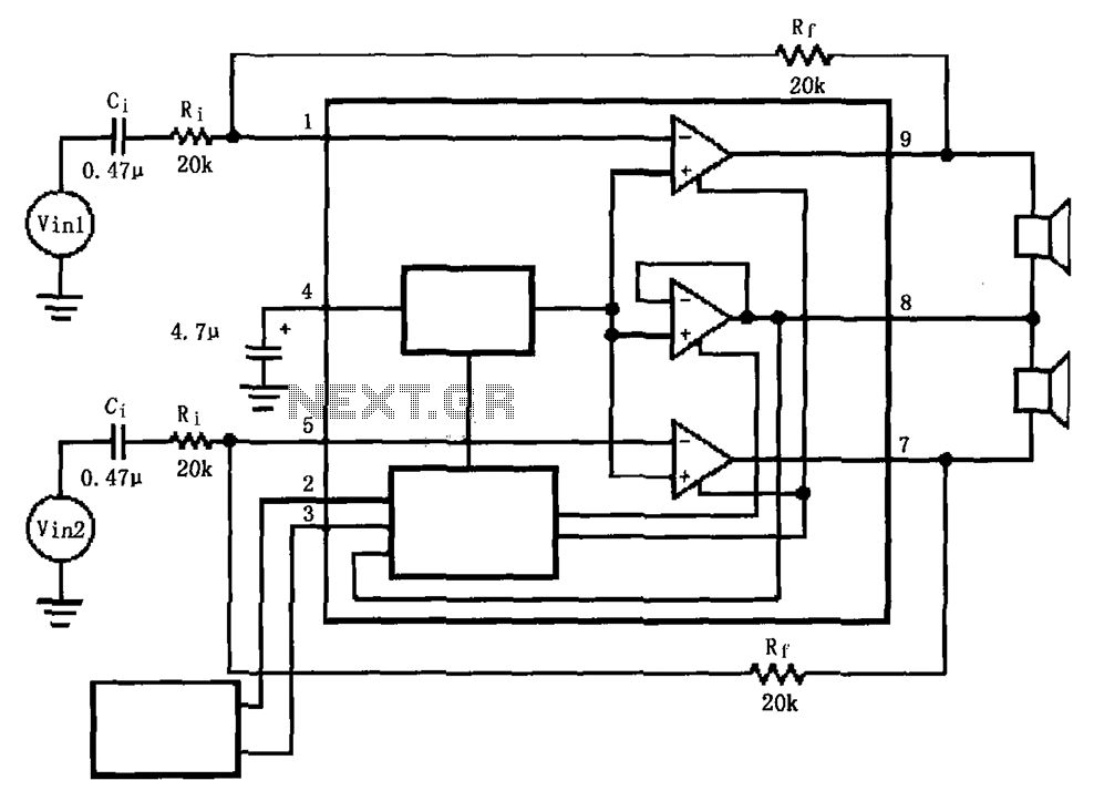
The LM4911 is presented in a configuration that does not utilize an output capacitor (OCL) for its power circuit. This design eliminates the need for squelch control (Mute), as the shutdown control (SD) responds more rapidly than the squelch...
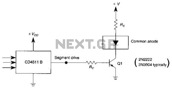
The use of a switching transistor, such as a 2N2222 or 2N3904, enables the operation of the CD4511B with a common-anode display. The transistor should be selected to provide approximately 1 mA to drive Q1, while resistor Rr must...
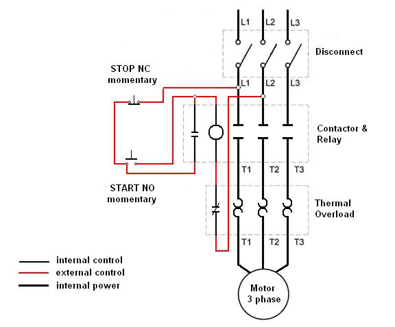
Wiring a three-phase motor through a two-pole vacuum switch involves two lines passing through the switch while one line remains continuously energized to the motor. Is this configuration correct, or does it present a safety concern? When wiring a three-phase...
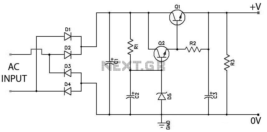
Low Ripple Regulated Power Supply Circuit Diagram. This circuit can be employed in applications requiring high current with minimal ripple voltage, such as in high-powered class AB amplifiers where high-quality audio reproduction is essential. The low ripple regulated power...
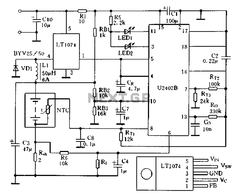
Charging circuit from the DC power supply switching power supply control The charging circuit described is designed to operate with a DC power supply, utilizing a switching power supply control mechanism. This type of circuit is commonly employed in applications...

The system consists of an LK16-5/31 type master controller and a PQY1 Series magnetic control panel, which includes a control circuit. The motor is controlled by limit switches SQ1 and SQ2, which manage the reverse operation. The master controller...
Warning: include(partials/cookie-banner.php): Failed to open stream: Permission denied in /var/www/html/nextgr/view-circuit.php on line 713
Warning: include(): Failed opening 'partials/cookie-banner.php' for inclusion (include_path='.:/usr/share/php') in /var/www/html/nextgr/view-circuit.php on line 713