
Shaking electronic LED Dice

The electronic LED dice project utilizes a mechanical trigger mechanism to simulate the action of traditional dice. The primary components include a 16F688 microcontroller from Microchip, which serves as the central processing unit for the device. The microcontroller is programmed to control the LED outputs and generate sound through a piezo buzzer based on the input from the mechanical trigger.
The mechanical trigger consists of a spring and a wire contact. The spring is mounted in a way that allows it to move freely within the enclosure when the device is shaken. A screw is attached to the end of the spring, providing additional weight that ensures the spring remains in contact with the wire when the device is stationary. The design requires careful consideration of the spring's stiffness to ensure it does not bend under its own weight while still being sensitive enough to activate upon shaking.
When the device is activated, the microcontroller initializes the circuit, lighting all LEDs in a sequential pattern to simulate the rolling of the dice. The LEDs are arranged in a manner similar to traditional dice faces, with each LED representing a potential outcome. The piezo buzzer emits sound during the "rolling" phase, enhancing the interactive experience. Once the microcontroller registers the mechanical trigger activation, it randomly selects a number corresponding to the illuminated LEDs, simulating the roll of a die.
The circuit is powered by two AAA batteries, housed within a battery support system, ensuring portability and ease of use. The resistors (R1 to R7 at 500 ohms and R8 at 10K ohms) are employed to limit current to the LEDs and protect the microcontroller. A 100nF capacitor (C1) is included for decoupling purposes, ensuring stable operation of the microcontroller by filtering out voltage spikes.
The entire assembly is mounted on a printed circuit board (PCB) within a compact box, designed to withstand the mechanical action of shaking. The inclusion of an on/off switch (S1) allows for convenient power management. This innovative approach to creating a motion-controlled LED dice provides an engaging and interactive experience without the need for costly accelerometers, making it an accessible project for electronics enthusiasts.I've always wanted to build an electronic led dice, but something different from what we see on the internet. Making it motion controlled... now that's new! Many new cell phones that have accelerometers built in also have dice games. These dice move when shaking the cell phone. My Led Dice project will also work with a shake motion but without the use of the expensive accelerometers.
The trigger is a mechanical device and it will sense the shaking movement. One contact will be on a spring and the other contact will be on a wire. The spring has a screw on it's end and it will act as a weight. Placing the box on it's side, the spring needs to have enough strength not to bend with it's own weight. Shaking will make the spring to move and touch the wire closing the circuit and this way the microcontroller will know when it's time to roll the dice.
urning on the circuit, the microcontroller will initialize and light on and off all leds. Shaking the box will roll the dice. The leds will simulate the rolling of the dice and the piezo will sound until the final number is displayed. Once the final number is displayed it's possible to sort another number simply by shaking the box again.
Parts: R1 500 ohms resistor R2 500 ohms resistor R3 500 ohms resistor R4 500 ohms resistor R5 500 ohms resistor R6 500 ohms resistor R7 500 ohms resistor R8 10K resistor C1 100nF cap Led1 to 7 5mm flat led Piezo Piezo HPE-120 IC1 16F688 microcontroller from Microchip S1 Normal On/Off switch Others: Box AAA x2 battery support PCB Spring, screws and wire Hex program for the microcontroller 🔗 External reference
Related Circuits
The LED circuit below is an example of using 25 white LEDs in series connected to the 120VAC line. It can be modified for more or less LEDs by adjusting the resistor value. The exact resistance will depend on...
This Project Multi-Pattern Running light is used to generate several designs of Running Lights. We use ten LEDs for display. The designs can be selected by using two switches UP and DOWN. The 8 bit Microcontroller is used to...

A high-quality QRP transmitter, named NEXUS 6, is designed to explore issues related to extremely narrow bandwidth communication. This device is not merely a simplified version of a QRP transmitter; it aims to create a cost-effective system that can...
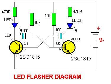
2SC1815 Flip Flop LED Flasher is a very simple and easy-to-understand circuit. The 2SC1815 Flip Flop LED Flasher circuit utilizes a 2SC1815 transistor, which is a general-purpose NPN transistor, to create a basic LED flasher. This circuit operates on the...
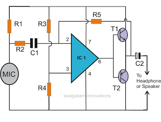
This document discusses the creation of an electronic spy bug circuit using two methods: one involving a wired connection from the transmitter to the receiver, and the other being a completely wireless setup capable of eavesdropping on conversations up...
This document presents the circuit diagram of an IC-controlled emergency light with a charger, which functions as a 12V to 220V AC inverter circuit. The primary features of this circuit include automatic activation of the light during mains failure...