
25 white LED Driver
Next we can work out the peak LED current to determine the resistor value. If the LED current is 20mA RMS, the peak current will be 20*1.414 or 28mA. But since the duty cycle is only 71 percent, we need to adjust this figure up to 28/0.71 = 39mA. So, the resistor value should be 95/.039 = 2436 ohms (2.4K) and the power rating will be .02^2 *2400= .96 watts. A two watt size is recommended.
Now this circuit can also be built using 2 diodes and a resistor as shown in the lower drawing. The second diode in parallel with the LEDs is used to avoid a reverse voltage on the LEDs in case the other diode leaks a little bit. It may not be necessary but I thought it was a good idea.
Working out the resistor value is similar to the other example and comes out to about half the value of the full wave version, or about 1.2K at 1 watt in this case. But the peak LED current will be twice as much or about 78mA. This is probably not too much, but you may want to look up the maximum current for short duty cycles for the LEDs used and ensure 79mA doesn't exceed the spec.
The described LED circuit utilizes 25 white LEDs connected in series to a 120VAC supply, rectified using a bridge rectifier to convert the AC voltage to DC. The forward voltage drop of each LED is approximately 3 volts, resulting in a total voltage drop of 75 volts across all LEDs when in operation. The remaining voltage across the resistor, calculated to be 95 volts, is determined by subtracting the total LED voltage from the peak rectified voltage of 170 volts.
The operation of the circuit is characterized by a non-continuous current flow through the resistor, which only conducts when the input voltage exceeds the LED forward voltage. This results in a duty cycle of approximately 71 percent, which indicates that the resistor will conduct current for about 64 degrees of the 90-degree half-wave rectified cycle.
To calculate the appropriate resistor value, the peak LED current must be considered. Starting with a desired RMS current of 20mA, the peak current is derived using the conversion factor for RMS to peak, yielding a peak current of 28mA. Adjusting for the duty cycle results in an effective peak current of 39mA, leading to a calculated resistor value of approximately 2436 ohms, rounded to a standard 2.4K ohm resistor. The power rating for this resistor is calculated to be around 0.96 watts, thus a 2-watt resistor is recommended to ensure reliability and account for any potential power surges.
An alternative circuit configuration involves using two diodes alongside the resistor. The second diode is connected in parallel with the LED array to protect against reverse voltage that may occur if the first diode experiences leakage. This configuration may not be strictly necessary but serves as a precautionary measure.
In this alternative setup, the resistor value is approximately half that of the full-wave configuration, calculated to be around 1.2K ohms with a power rating of 1 watt. This configuration will result in a peak LED current of approximately 78mA, which should be verified against the maximum current specifications of the individual LEDs to prevent exceeding their rated limits during operation.The LED circuit below is an example of using 25 white LEDs in series connected to the 120VAC line. It can be modified for more or less LEDs by adjusting the resistor value. The exact resistance will depend on the particular LEDs used. But working out the resistor value is a bit complicated since current will not continously flow through the resistor. In operation, the output of the bridge rectifier will be about 120 DC RMS or 170 volts peak. If we use 25 white LEDs with a forward voltage of 3 volts each, the total LED voltage will be 75 volts.
The peak resistor voltage will be 170- 75 or 95 volts but the resistor voltage will not be continous since the input must rise above 75 before any current flows. This (dead time) represents about 26 degrees of the 90 degree half wave rectified cycle, (asin) 75/170 = (asin) .44 = 26 degrees. This means the resistor will conduct during 90-26 = 64 degrees, or about 71 percent of the time. Next we can work out the peak LED current to determine the resistor value. If the LED current is 20mA RMS, the peak current will be 20*1.414 or 28mA. But since the duty cycle is only 71 percent, we need to adjust this figure up to 28/0.71 = 39mA. So, the resistor value should be 95/.039 = 2436 ohms (2.4K) and the power rating will be .02^2 *2400= .96 watts.
A two watt size is recommended. Now this circuit can also be built using 2 diodes and resistor as shown in the lower drawing. The second diode in parallel with the LEDs is used to avoid a reverse voltage on the LEDs in case the other diode leaks a little bit. It may not be necessary but I thought it was a good idea. Working out the resistor value is similar to the other example and comes out to about half the value of the full wave version, or about 1.2K at 1 watt in this case.
But the peak LED current will be twice as much or about 78mA. This is probably not too much, but you may want to look up the maximum current for short duty cycles for the LEDs used and insure 79mA doesn't exceed the spec. 🔗 External reference
Related Circuits
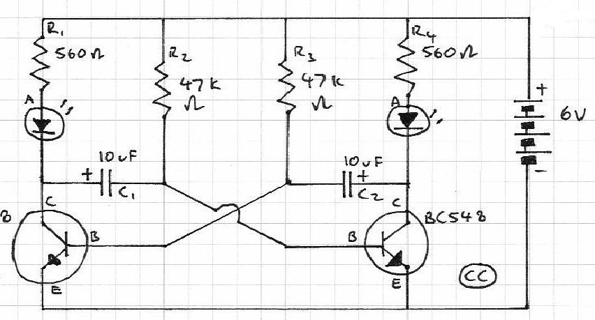
When the preset is set to its maximum, the LED flashes approximately every half second. This flashing rate can be increased by using a larger capacitor value, for instance, changing from 10µF to 22µF will result in a flashing...
This document outlines the theory behind a high-speed control scheme for an LED display screen circuit. The circuit utilizes the MCS51 series microcontroller to manage the LED display. A 62512 random access memory (RAM) is employed for data storage,...
The power failure light that I eventually designed and built is housed in the plastic case from a wall-mounted power transformer. I had accidentally destroyed the transformer by shorting its output, and had kept the plastic case for years,...
Blinks 2 LEDs in sequence. An explanation of its operation is requested. It is understood that a capacitor charges, causing the LED to turn off, and when it discharges, the LED turns on. However, clarification on the purpose of...
A pulsating light is used for signaling purposes with a voltage of 230V. A simple circuit has been designed, consisting of an LED diode, two capacitors, two resistors, a diac, and a diode. The operation of the circuit is...
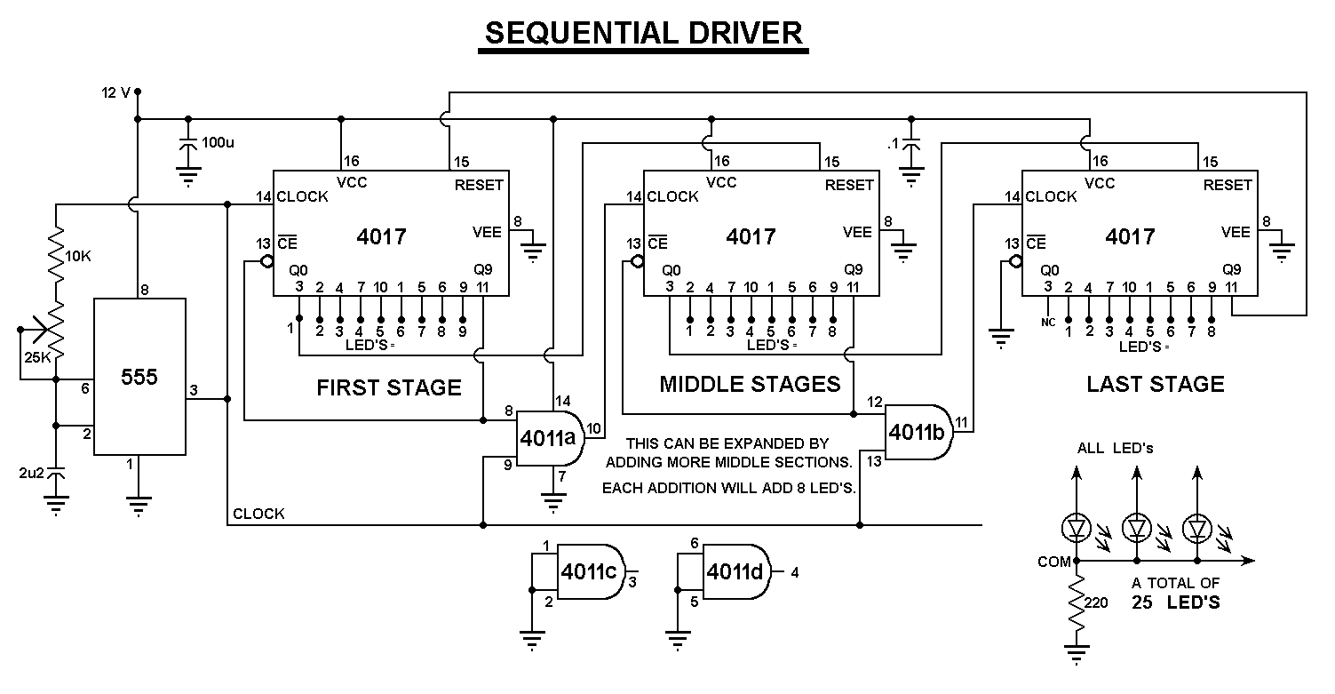
All LED negatives are connected to the "COM" pad, then through a 220 Ohm resistor to ground. There is no need for additional current limiting resistors, even with supply voltages up to 16 volts. The described circuit employs a simple...