
Deluxe Crystal Controlled Transmitter

The NEXUS 6 QRP transmitter circuit is designed with precision and functionality in mind, focusing on achieving a high-quality communication system capable of operating within extremely narrow bandwidths. The schematic incorporates a series of stages, including an oscillator, modulator, and amplifier, all optimized for minimal phase noise and harmonic distortion. The oscillator stage utilizes a crystal-controlled design to ensure frequency stability, which is critical for narrow bandwidth operations.
The modulator stage employs a direct conversion technique, enabling efficient signal processing while maintaining low distortion levels. The use of discrete components, such as BJTs or FETs, enhances the reliability and serviceability of the circuit. Each component's selection is made with careful consideration of its performance characteristics, ensuring that the overall system maintains linearity across the desired frequency range.
The amplifier stage is configured to provide sufficient gain while incorporating feedback mechanisms to suppress unwanted harmonics. This is achieved through a combination of passive components that form low-pass filters, allowing only the desired frequency components to pass while attenuating higher-order harmonics.
Coils and transformers, although minimized in the design, are strategically placed to address impedance matching and signal integrity issues. The bandpass filter is designed to isolate the desired operating frequency, ensuring that the transmitter operates efficiently within its designated bandwidth.
The NEXUS 6 is engineered to accommodate a wide frequency range from 1 to 30 MHz, making it versatile for various applications. The careful design considerations allow the transmitter to be used effectively in QRSS operations, where low power and narrow bandwidth communication are paramount. This adaptability is particularly advantageous for amateur radio operators seeking to experiment with different frequency bands while maintaining high communication standards.
Overall, the NEXUS 6 QRP transmitter represents a thoughtful integration of engineering principles, practical design, and user accessibility, making it a valuable tool for radio amateurs and a significant contribution to the field of narrow bandwidth communication.A high quality QRP transmitter, which I have named as NEXUS 6, in my try to explore the issues related to extremely narrow bandwidth communication. It is not just another QRP transmitter on a diet and I will explain why. The goal is to build a cost effective system that couldbe easily reproduced by radio amateurs, yet using simple circuit topologies that can make this system a high quality one.
Extremely narrow bandwidth, phase noise, harmonic suppression and distortion are greatly considered. These parameters are not always easy to combine, as each parameter may cancel the others. Discrete components were used where possible. Using discrete components you ensure that your construction will always be able to be serviced (as long as discrete transistors exist).
Building a high quality construction is not as easy as the Medifast diet, and burning out a component that is 20 years old may not be the best thing to do especially if this component is a specific microchip that has been discontinued. The consideration about coils is very important too. Coils and high frequency ferrite transformers are almost an essential part of any serious RF construction, as they solve many of the inter-circuit problems, but many radio amateurs do not have the right cores and the skills to build complex transformers neither the equipment to test them.
In some cases, impedance mismatching is not very crucial, especially in HF bands so some transformers could be replaced with more commonly available components. In Nexus 6, I try to avoid using coils where I can. Unfortunately some coils, (like the bandpass filter or the broadband transformers) are essential and cannot be omitted.
Many radio amateurs seem to ignore factors like phase noise, distortion, harmonics suppression and bandwidth in their systems. For example, as long as a transmitter transmits they do not care about such factors too much. But if you talk about ultra low bandwidth or if you use the Nexus 6 as a backend for a microwave system, then you should consider these.
Nexus 6 has been designed for QRSS operation and to test my CDW data transfer system that I have built. These systems need no more than a few hertz or tens of hertz to exchange information and they could be considered as the only fail-safe way to transfer information in ultra long distances using ultra low bandwidth.
If everything else fails they will work! Another point is that most of the QRP circuits that I have seen for shortwave is for a single band or for a few bands. In my approach I am trying to make a continuous coverage broadband system which can operate from about 1-30MHz.
Making a broadband system without using complex broadband transformers is not easy and even if you succeed then you may need to carefully chose the components to ensure that the system will be as linear as possible throughout the HF bands. Broadband systems and harmonic suppression are difficult and expensive to accomplish. Sharp variable filters may be needed and this is not an easy and cheap task. The techniques used in NEXUS 6 try to reduce unwanted harmonics without compromising the broadband behavior of the circuit and without raising the budget and complexity too much.
I have found many circuits on the web that did not work satisfactorily or they did not work for me at all. So I decided to use the working ones and perform my own adjustments to suit my needs. If you build the Nexus 6 the way I describe you, it will work. I have performed months of tests in order to build a good working system so please do not judge easily before you study or build the circuit by yourself.
Everything in the schematic has been there for a reason and there is nothing that is not needed. Since I am a hobbyist in electronics though, I will be glad to discuss with you any points you think that should have been done better, so 🔗 External reference
Related Circuits
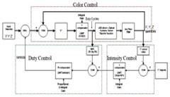
The system utilizes RGB LED light sources, an optical sensor, and a feedback controller. The purpose of employing optical feedback is to ensure color stability over temperature variations, maintain constant brightness, and control any specific color point or brightness...
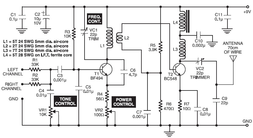
The transmitter circuit described here includes an additional RF power amplifier stage following the oscillator stage, which increases the power output to 200-250 milliwatts. When used with a properly matched 50-ohm ground plane antenna or a multi-element Yagi antenna,...
A high-quality FM transmitter circuit designed for use with amplifiers, providing a strong signal strength with a range of up to 500 meters and a power output of approximately 200 mW. This FM transmitter circuit is engineered to deliver reliable...
This project provides a simple temperature-controlled fan. If the difference between the actual temperature and the user-defined temperature is significant, the fan will operate. The temperature-controlled fan circuit utilizes a temperature sensor, a microcontroller, and a fan motor to regulate...
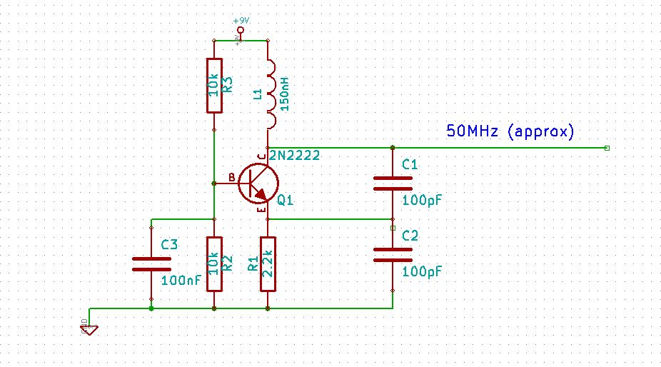
Similar to a square wave, interference with radios can lead to public discontent and may attract the attention of licensing authorities, which should be avoided. A Colpitts oscillator is recommended, featuring a "tank circuit" composed of inductance (L) and...
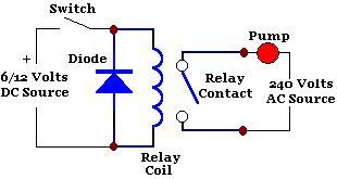
A relay is an isolated switch, with no direct connection between the switching device and the load. Relays are commonly used to control high-voltage devices, protecting sensitive low-voltage components from damage. Various types of relays exist, but electromechanical relays...