
Shed/Garage Alarm
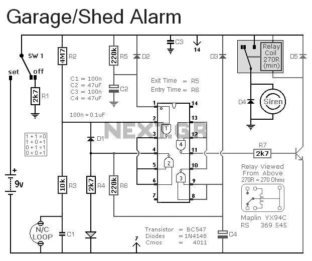
This burglar alarm circuit is designed for simplicity and effectiveness, providing an essential security feature for residential or small commercial applications. The circuit employs a standard configuration that includes a microcontroller or timer IC for managing the timing functions, alongside a relay to control the siren. The use of normally-closed input devices ensures that the circuit remains in a stable state until an intrusion is detected, at which point the circuit is disrupted, triggering the alarm.
The design is optimized for low power consumption, making it suitable for battery operation, which is critical in ensuring continuous monitoring without the need for frequent battery changes. The choice of input devices allows for flexibility in installation, accommodating various entry points such as doors and windows. The adjustable timing feature through R5 and R6 not only personalizes the alarm system but also enhances usability, allowing users to configure the system according to their daily routines.
The inclusion of an LED indicator provides visual feedback, enhancing user experience by confirming the status of the alarm system. The circuit layout should be carefully designed to minimize noise and interference, ensuring reliable operation in diverse environments. Proper placement of components and routing of connections will also contribute to the overall performance and longevity of the burglar alarm system.This is a simple single-zone burglar alarm circuit. Its features include automatic Exit and Entry delays. It`s designed to be used with the usual types of normally-closed input devices such as - magnetic-reed contacts - micro switches - foil tape - and PIRs. It has an extremely small standby current - making it ideal for battery-powered operation. I`ve used a 9-volt battery in the diagram - but the circuit will work at anything from 5 to 15-volts. Just choose a relay and Siren suitable for the voltage you want to use. It`s easy to use. To set the alarm move SW1 to the "set" position. You now have about 10 to 15 seconds to leave the building. When you return and open the door - the green LED will light. You then have about 10 to 15 seconds to move SW1 to the "off" position. If you fail to do so - the relay will energize and the Siren will sound. Of course - you can turn the Siren off at any time by moving SW1 to the "off" position. Because of manufacturing tolerances - the precise length of any delay depends on the characteristics of the actual components you`ve used in your circuit.
But by altering the values of R5 & R6 you can adjust the Exit and Entry times to suit your requirements. Increasing the values increases the time - and vice-versa. 🔗 External reference
Related Circuits
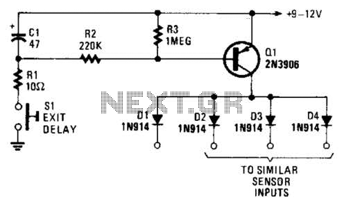
Depressing SI charges CI to the supply voltage. This biases Q1 on via bias resistors R2 and R3. A voltage is available for the duration of the delay period to hold off the alarm circuit. CI can be increased...
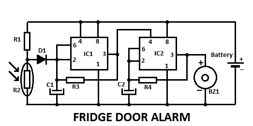
This fridge door alarm operates using a 3V battery supply and should be placed in a small box inside the fridge, near the lamp or close to the opening. The fridge door alarm circuit is designed to alert users...
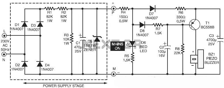
This is a specialized circuit design for a power supply failure alarm. Most power supply failure alarm or indicator circuits require an independent power supply. However, the alarm circuit presented here... The power supply failure alarm circuit is designed to...
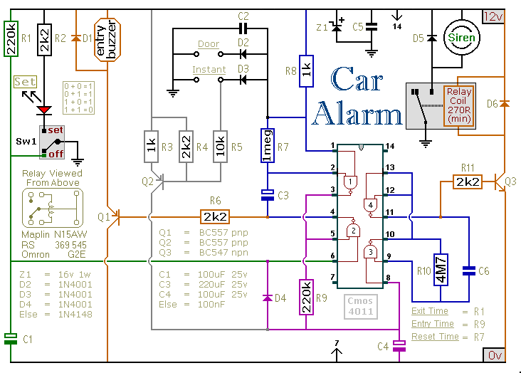
This car alarm circuit includes exit and entry delays, an instant alarm zone, an intermittent siren output, and automatic reset. By incorporating external relays, it is possible to immobilize the vehicle and activate the flashing lights. The car alarm circuit...
Almost trivial application of an AT90S2313 or ATtiny2313 in an alarm clock to change the alarm from "BEEP BEEP BEEP BEEP BEEP BEEP BEEP BEEP..." to "WAKE UP" in Morse code. This was designed in response to a request...
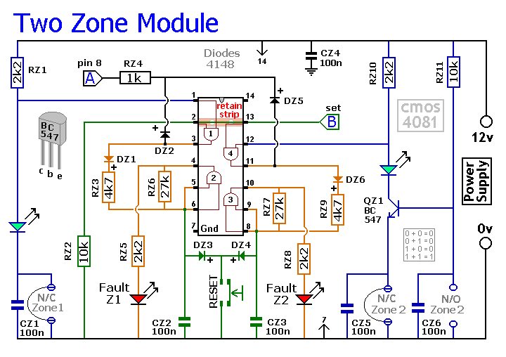
The Basic Alarm Circuit features an automatic Exit/Entry Zone, which includes an Instant Alarm Zone capable of accepting both normally-closed and normally-open triggering devices, alongside an "Always On" 24-hour Personal Attack/Tamper Zone. Expansion Modules can be used to add...