
Morse Code Alarm Clock
The circuit utilizes an AT90S2313 or ATtiny2313 microcontroller, which is programmed to output the "WAKE UP" message in Morse code. The microcontroller operates primarily in a low-power sleep mode, consuming only microamps until it is triggered by an interrupt signal. Upon waking, it generates timing loops to create the Morse code output. The interrupt is activated by a 2 kHz square wave signal on pins 14 and 15, which are configured to be 180 degrees out of phase. This configuration produces a square wave with a peak-to-peak voltage of approximately 6 volts, effectively driving the connected speaker.
A 100 µF capacitor is placed in series with the speaker to prevent DC power from being drawn, allowing only the AC signal to pass through. After transmitting the Morse code message, the microcontroller returns to its low-power state. The digital inputs of the microcontroller are pulled high using the internal pull-up resistors, minimizing overall power consumption.
The clock module operates from a single AA cell, providing 1.5 volts. To ensure that the AT90S2313 receives adequate voltage, a second AA cell is added, supplying the necessary 2.7 volts or higher. The alarm signal is extracted from the clock's speaker circuit. When the alarm signal transitions to ground, a 2N4401 transistor is activated, sinking sufficient current to pull the interrupt pin low. A 39 kΩ resistor is connected to the base of the transistor, controlling the base current to approximately 20 µA, which is sufficient given the weak pull-up on pin 6 of the microcontroller.
The 2N4401 transistor amplifies the alarm signal from the clock module, converting the 1.5 volts peak-to-peak signal to a higher swing that is compatible with the microcontroller's power supply. A 0.22 µF capacitor is used to clean up the signal at the collector, ensuring that it goes low when the alarm signal is detected and remains low for about 2 milliseconds after the last beep.
A crystal oscillator is employed for clock generation since the AT90S2313 lacks an internal oscillator. Although this setup works, a more efficient option could be using an ATtiny12 with its internal oscillator. The 100 µF capacitor can potentially be omitted if firmware adjustments are made to ensure that pins 14 and 15 are in the same state (either high or low) when no tone is being generated.
The speaker used in this application is a high impedance piezoelectric transducer, which measures greater than 20 MΩ. It is critical to select a speaker with sufficient impedance—preferably above 150 Ω DC—to prevent excessive current draw, which should not exceed 40 mA when driven by the 6 volts peak-to-peak signal.(Almost) Trivial application of an AT90S2313 or ATtiny2313 in an alarm clock to change the alarm from "BEEP BEEP BEEP BEEP BEEP BEEP BEEP BEEP..." to "WAKE UP" in Morse code. This was designed in response to a request and is in daily use. An inexpensive alarm clock was modified by installing a small circuit board inside the clock body and attaching some wires to the clock's circuit board.
The second AA cell needed to bring the voltage up to 3 volts for the micro controller is mounted on the back. The high impedance speaker was temporarily mounted on the top as I pondered where the best permanent location would be, and like many decisions that are delayed with the aid of a temporary fix, its still waiting final disposition.
The micro controller sleeps most of the time, consuming mere micro amps until it receives an interrupt. and wakes up, then, using timing loops, it generates timing for "WAKE UP" in Morse code. Interrupts provide a 2 kHz square wave on pins 14 and 15 that are 180 degrees out of phase with one another (when one pin is high, the other pin is low), which means that the speaker sees a square wave that is nearly 6 volts peak-to-peak (or 3 volts RMS since it is a square wave).
The 100 uf capacitor in series with the speaker keeps it from drawing any DC power. Once the "WAKE UP" message has been sent, the micro controller goes back to sleep. The digital inputs are pulled high with the chips' weak internal pull-ups to minimize power dissipation. The speaker outputs are configured as outputs (I hope that is not a surprise). The clock module runs from a single 1.5 volt AA cell. To raise the voltage to 2.7V or greater to run the AT90S2313, I added a second AA cell that only powers the AT90S2313.
The alarm signal is taken from one of the wires from the alarm clock module to the clock's speaker. When the signal swings to ground, the 2N4401 in the alarm module sinks enough current to pull the interrupt pin low. The 39k resistor on the base of the 2N4401 sets the base current to (1.5V-0.7V)/39k = 20 micro amps. The weak pull-up on pin 6 supplies less than 85 micro amps when grounded, with 30 micro amps being typical, so the base drive is more than sufficient.
Notice that this transistor's main function is to amplify the 1.5 V peak-to-peak signal from the alarm module to one that swings from ground to the micro controllers' positive power supply. The 0.22 uf capacitor cleans up the signal on the collector so that the collector goes low when the alarm signal comes in and stays low for about 2 milliseconds after the last beep.
A crystal oscillator was used because I have a whole lot of AT90S2313's and they don't have an internal oscillator. A better choice would be something like an ATtiny12 running with its internal oscillator. While on the subject of what could be better, the 100 uf capacitor can be eliminated provided that the firmware is modified to assure that pins 14 and 15, which drive the speaker, are in the same state (high, low, as inputs) when the tone is not being sounded or that at least one of them is configured as an input when the tone is not being sounded.
A note about the speaker: I used a high impedance transducer that I picked up at a surplus store. I was told that it is piezoelectric and appears to be so as it measures as greater than 20 Megohms on my ohmmeter. Be careful to use a piezoelectric transducer or other type of speaker with high enough impedance to feel comfortable that the current through it will not exceed 40 milliamps when driven by a 6 volt peak-to-peak signal.
Anything measuring higher than 150 Ohms DC would fulfill this if it does not have a large shunt capacitance. 🔗 External reference
Related Circuits
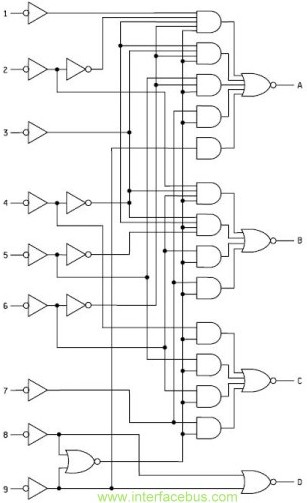
This function is not complex and can be easily implemented in a Programmable Logic Device (PLD) or Field Programmable Gate Array (FPGA). However, implementing this function in a small PLD may consume most of the device's I/O pins, which...
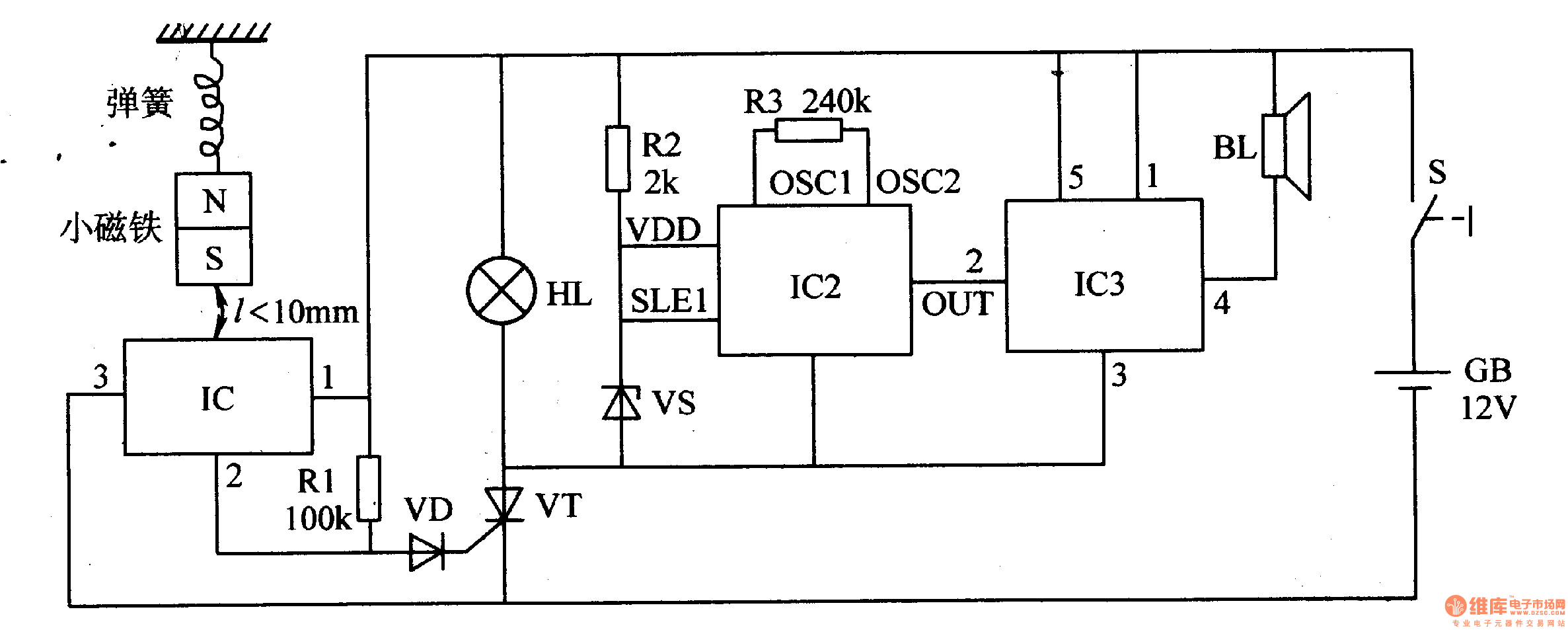
When the switch is activated, the seismic alarm enters a detection mode. In the absence of an earthquake, pin 3 of IC1 outputs a low signal, resulting in the disconnection of VT, which keeps the alarm circuit inactive. Upon...
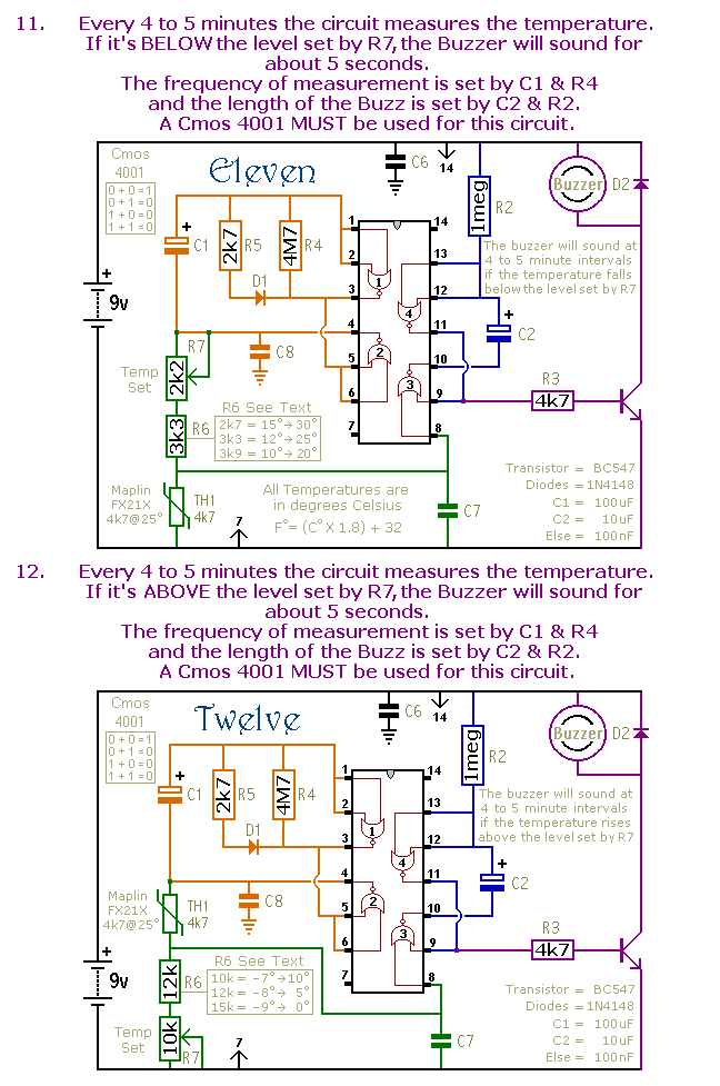
This is a selection of small self-contained alarm circuits. They have a very low standby current; and are suitable for battery operation. The described alarm circuits are compact and designed for low power consumption, making them ideal for battery-powered applications....
This is a fire alarm circuit that utilizes a Light Dependent Resistor (LDR) to detect smoke from a fire, making it effective for identifying dark smoke. The risk of fire accidents increases during the summer season, and such incidents...
This circuit features a micro vibration sensor, a trigger delay circuit, and a control circuit, as illustrated in the accompanying figure. The micro vibration sensor comprises a vibration sensing device and a high power amplifier circuit, enabling it to...
The general-purpose circuit of the simple pressure sensor alarm is constructed using a few easily accessible and inexpensive components. The operation of this circuit is straightforward. The simple pressure sensor alarm circuit typically includes a pressure sensor, an operational amplifier...