
Signal and Tone Activated Relay Switch

The circuit described functions as a sensitive switch designed to detect low-level AC signals, specifically those above 5 mV, which is critical for applications involving audio signals, such as voice detection. The operational frequency range of the circuit spans from 50 Hz to 3 kHz, aligning with the frequency characteristics of human speech. This feature enables the circuit to be particularly useful in voice-activated systems or audio processing applications.
The RV1 trimmer potentiometer allows for fine adjustments to the circuit's sensitivity, ensuring that the relay (RL1) remains off when no significant input signal is present. This prevents false triggering caused by noise or other unintended signals. When a valid input signal is detected, the relay engages, allowing for further action within the circuit, such as activating an output device.
The band-pass filter depicted in Fig.2 is set to a center frequency of 1 kHz, which is optimal for filtering out unwanted frequencies while allowing the desired signal range to pass through. The integration of this filter into the feedback loop at points A, B, and C enhances the overall performance of the circuit by ensuring that it only reacts to signals within this frequency band. This selective sensitivity is crucial for applications where it is essential to isolate specific audio frequencies from a broader spectrum of signals.
The part list provides the necessary components for constructing the circuit. Key components include resistors (R1, R2, R3, R4, R5, R7, R8, R9), capacitors (C1, C2, C3, C4, C5, C6), diodes (D1, D2), a transistor (Q1), an operational amplifier (IC1), and a relay (RL1). Each component plays a specific role, such as setting gain, filtering signals, or providing switching capabilities within the circuit. The inclusion of a BC214L transistor allows for signal amplification, while the LM741 operational amplifier is employed for signal processing tasks.
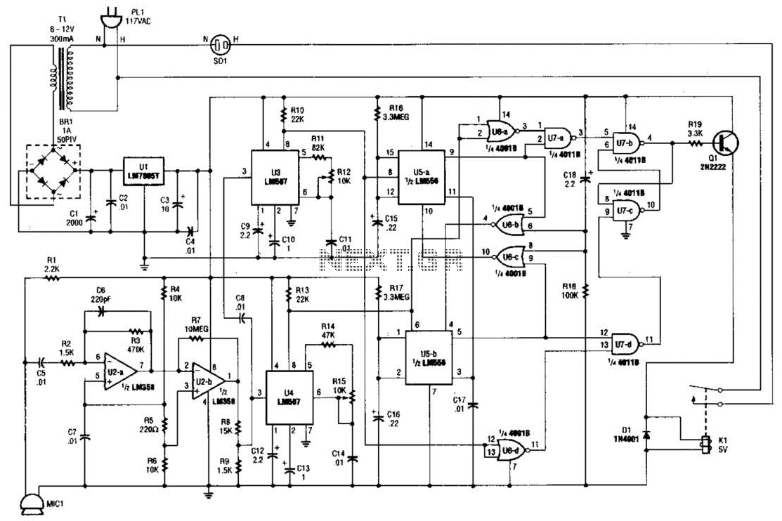
This circuit design is suitable for applications requiring precise control and detection of audio signals, making it a valuable tool in the field of electronics, particularly in audio engineering and voice recognition systems.In the Fig.1, exist a circuit, which is a sensitive switch that corresponds in AC signals of input, for signals above 5mV. Corresponds in all the signals from 50 HZ until 3KHZ, region in which found the human voice. The RV1 is regulated so much what RL1 it?s in situation OFF, when the input is it has null signal. In the Fig.2, exist a band - pass filter, coordinated in the 1KHZ, which can be placed in line in the bronchus of negative feedback, in points A, B, C, making sensitive the circuit only in this frequency.
Part List R1-2-6=10Kohm C1-2-3=100nF D2=1N4001 R3=1Mohm C4=47uF 16V Q1=BC214L R4=33Kohm C5-7=10nF IC1=LM741 R5=1Kohm C6=20nF [10nF//10nF] RL1=12V Relay >120ohm R7-8=15Kohm RV1=10Kohm TRIMMER R9=7.5Kohm [15K//15K] D1=1N4148 🔗 External reference
Related Circuits
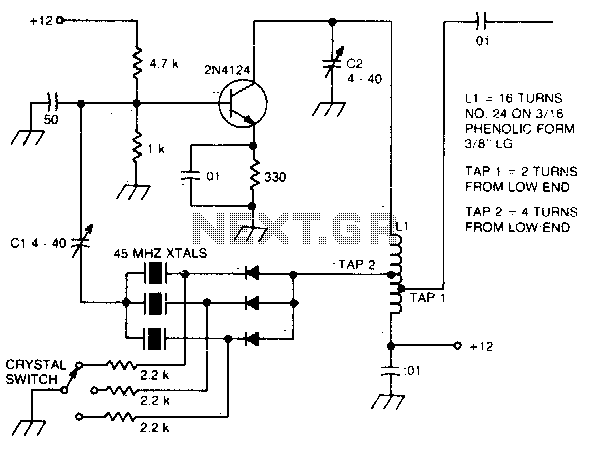
The large inductive phase shift of LI is compensated for by Cl. Overtone crystals have very narrow bandwidth; therefore, the trimmer has a smaller effect than for fundamental-mode operation. The statement discusses the compensation of inductive phase shifts in a...
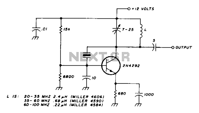
This oscillator is designed for overtone crystals in the 20-100 MHz range, operating in the third and fifth mode. The operating frequency is determined by the tuned circuit. The oscillator circuit is specifically tailored to utilize overtone crystals, which are...
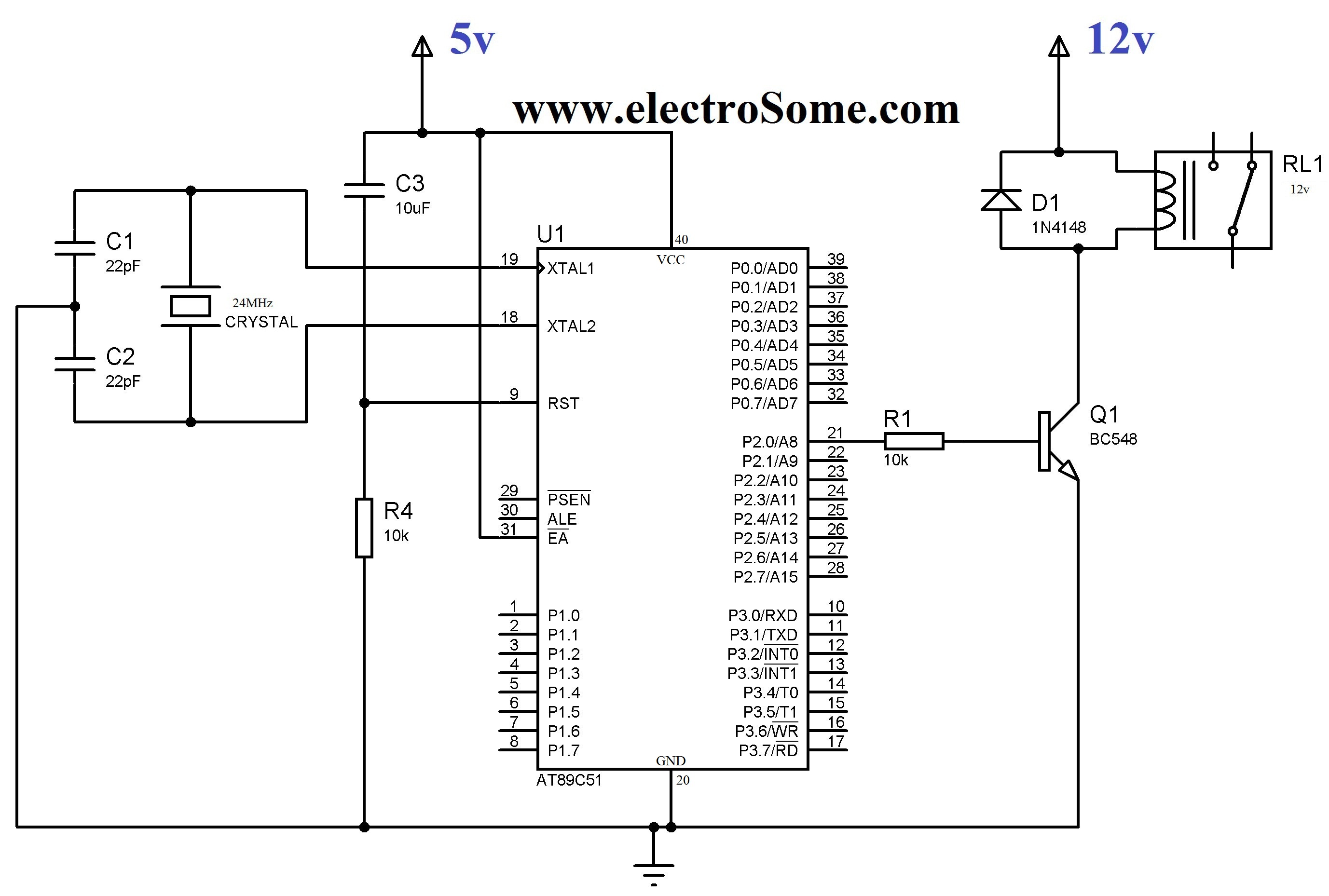
In various electronic applications, it is necessary to switch or control high voltages or high currents. In such instances, electromagnetic or solid-state relays may be utilized. For example, these relays can control home appliances using low-power electronic circuits. An...
Upon acquiring the car, it was appreciated that it did not emit a "chirp" or sound the horn each time the doors were locked or unlocked. There are occasions when discreetness is preferred regarding entering or exiting the vehicle....
The whistle switch features two tone detectors, each based on an LM567 tone decoder, requiring minimal additional components. It is designed to respond to two or more occurrences of a specific tone or sequence of tones within a defined...
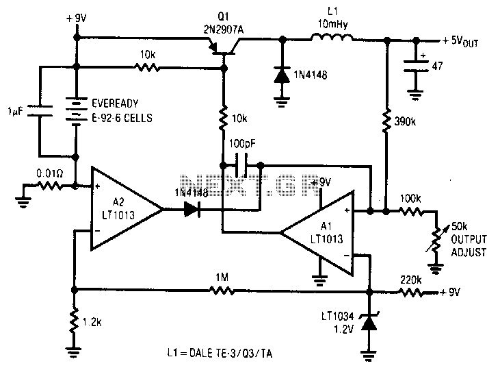
A simple battery-powered switching regulator provides 5 V output from a 9-V source with 80% efficiency and a 50 mA output capability. When Q1 is activated, its collector voltage increases, allowing current to flow through the inductor. This causes...