
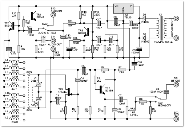
Signal Conditioner
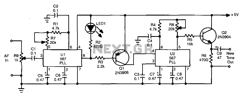
The circuit operates by first receiving an audio signal that may be compromised due to weak signal strength or interference. The phase-locked loop (PLL), designated as U1, plays a crucial role in signal processing by locking onto the frequency of the incoming tone. The frequency detection is achieved through the configuration of resistors R1 and R7 and capacitor C2, which set the PLL's reference frequency. When the PLL successfully detects a tone, it generates a low signal at pin 8.
This low output serves as a control signal that activates tone generator U2. The tone generator is responsible for producing a clean, consistent tone that can replace the original weak signal. The output of U2 can then be used for further processing or directly fed to a speaker or other audio output device. The overall design significantly enhances the clarity of CW signals by filtering out unwanted noise and static, making it a valuable tool for amateur radio operators and audio signal processing applications.
In summary, the circuit effectively recovers and enhances weak CW signals by utilizing a PLL for frequency detection and a tone generator for signal improvement, resulting in clearer audio output. This circuit takes audio from a receiver that might have a weak CW or tone signal and uses a PLL (Ul) to recover the wea k signal. Ul produces a low on receipt of a tone or note of frequency, determined by Rl, R7, and C2. The output of Ul (pin 8) goes low, keys tone generator U2, and produces a new tone. The circuit is useful in cleaning up CW reception in static, noise, etc. 🔗 External reference
Related Circuits
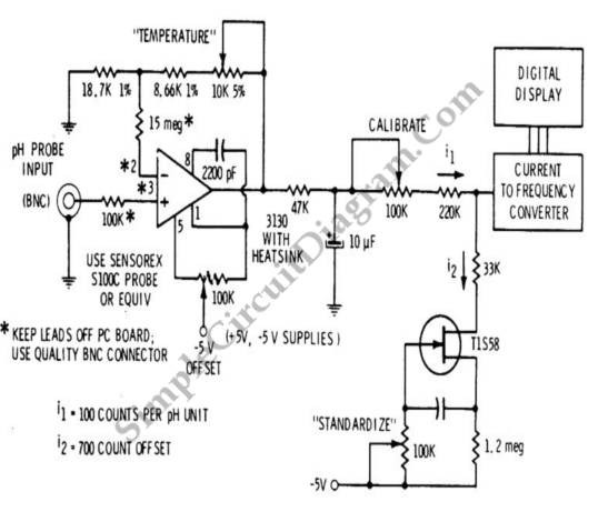
A signal conditioner for a pH meter probe requires high input impedance. The signal conditioning of the pH meter probe is achieved by incorporating a buffer. The design of a signal conditioner for a pH meter probe is critical for...
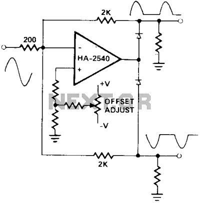
A circuit utilizing either the HA-2539 or HA-2540 in conjunction with two low-capacitance switching diodes can effectively separate signals exceeding 10 MHz. This configuration is particularly beneficial for applications such as full-wave rectification, AM detection, or synchronization generation. The described...
The CMX469A is a single-chip CMOS LSI circuit that functions as a full-duplex modem, supporting baud rates of 1200, 2400, or 4800. The mark and space frequencies for this modem are 1200/1800 Hz, 1200/2400 Hz, and 2400/4800 Hz, respectively....
This signal generator is designed for the realignment of radio receivers. It is an economical and straightforward unit, adequate for its intended application. However, the output is not a pure sine wave, which may limit its suitability for more...
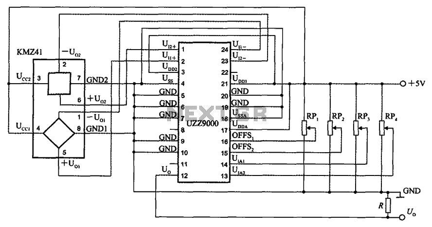
The UZZ9000 KMZ41 detection circuit is configured based on the voltage output type and angle. It operates with a +5V power supply. Potentiometers RP1 and RP2 are used for offset voltage adjustment, while potentiometers RP3 and RP4 are utilized...
Analog switches SL and SA disconnect the inverted logic signal to terminal 2. S1 and S4 are turned on, allowing capacitance between S1 and S8 to couple. S2 and S4 shunt with an on-state resistance ranging from 50 to...