
Digital pH Meter Signal Conditioner with Pulse/Frequency Output
The design of a signal conditioner for a pH meter probe is critical for accurate pH measurement. The high input impedance is essential to minimize the loading effect on the pH probe, ensuring that the probe's output signal is not significantly altered.
To achieve this, a voltage buffer, typically implemented using an operational amplifier (op-amp) configured as a voltage follower, is employed. This configuration allows the op-amp to provide a high input impedance while maintaining a low output impedance, thereby effectively isolating the pH probe from the subsequent circuitry.
In the schematic, the pH probe is connected to the non-inverting input of the op-amp. The output of the op-amp is then connected to the next stage of the signal conditioning circuit, which may include additional filtering and amplification stages, depending on the application requirements. Power supply decoupling capacitors should be placed close to the op-amp to ensure stable operation.
To further enhance performance, it is advisable to use a low-noise op-amp to reduce any potential interference that could affect the accuracy of the pH measurement. The use of precision resistors and capacitors in the feedback and input paths will also contribute to the overall stability and accuracy of the signal conditioning circuit.
In summary, the signal conditioning circuit for a pH meter probe must prioritize high input impedance through the use of a buffer, ensuring accurate and reliable pH measurements by preventing loading effects on the probe.A signal conditioner for pH meter probe is required to have high input impedance. The signal conditioning of the pH meter probe is done by providing a buffer.. 🔗 External reference
Related Circuits
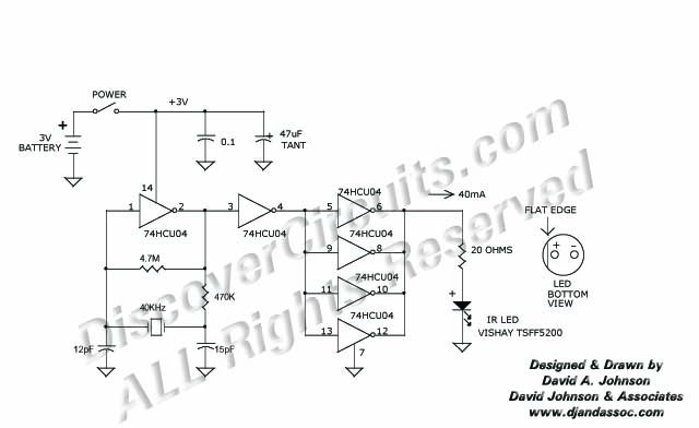
This 40 kHz crystal-controlled oscillator circuit drives an infrared LED with powerful 40 mA pulses. The circuit operates at a frequency of 40 kHz, determined by the crystal oscillator, which provides stable frequency output essential for applications requiring precise timing....
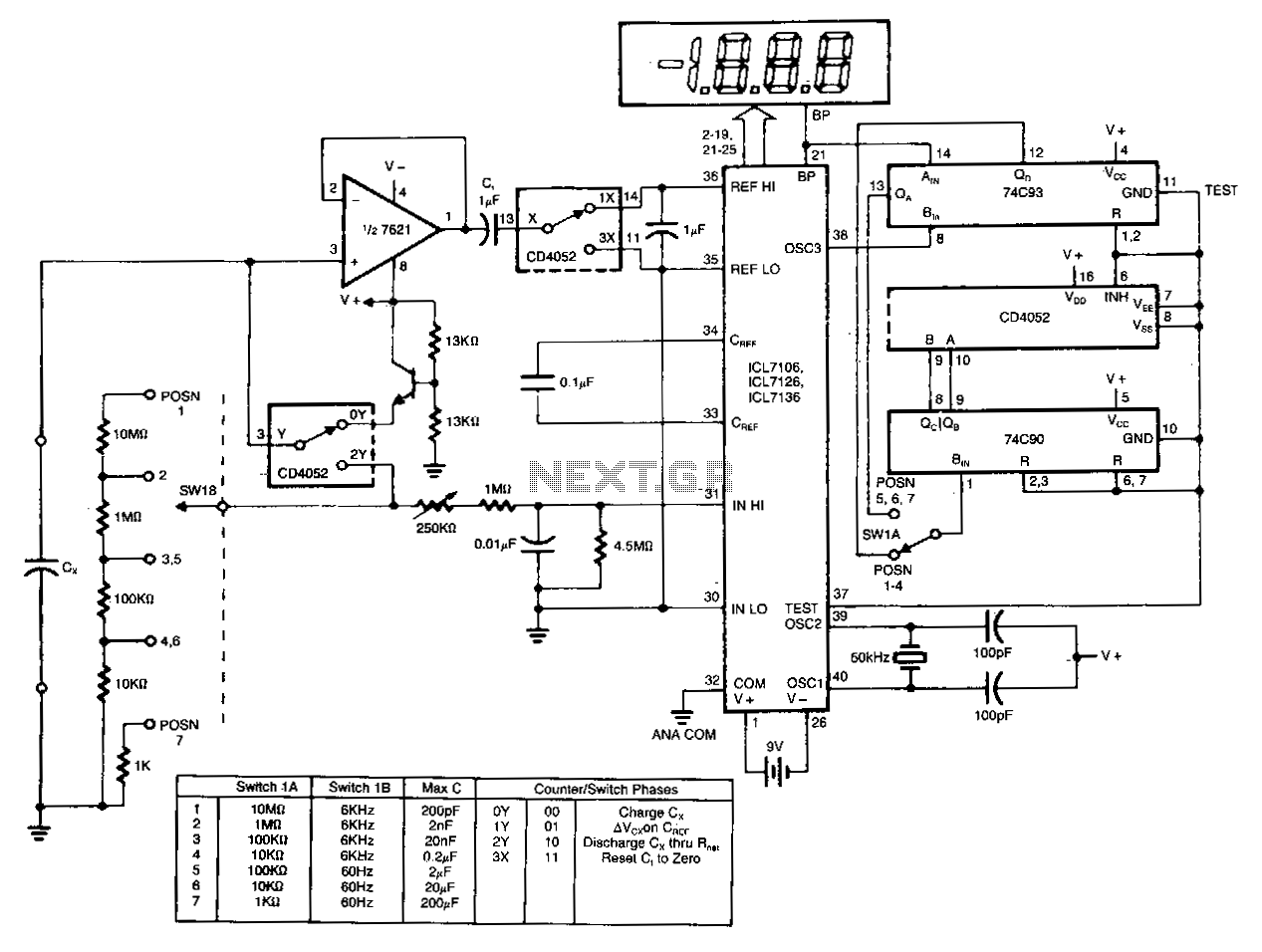
The circuit charges and discharges a capacitor at a crystal-controlled rate and stores the change in voltage achieved on a sample-and-difference amplifier. The current flowing during the discharge cycle is averaged and ratiometrically measured in the analog-to-digital converter (ADC)...
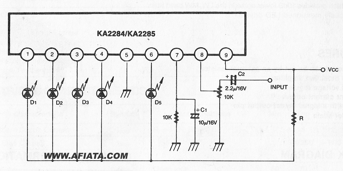
The KA2284 is a monolithic integrated circuit designed for 5-dot LED level meter drives with a built-in rectifying amplifier. It is suitable for both AC and DC level meters, such as VU meters or signal meters. The KA2284 integrated circuit...
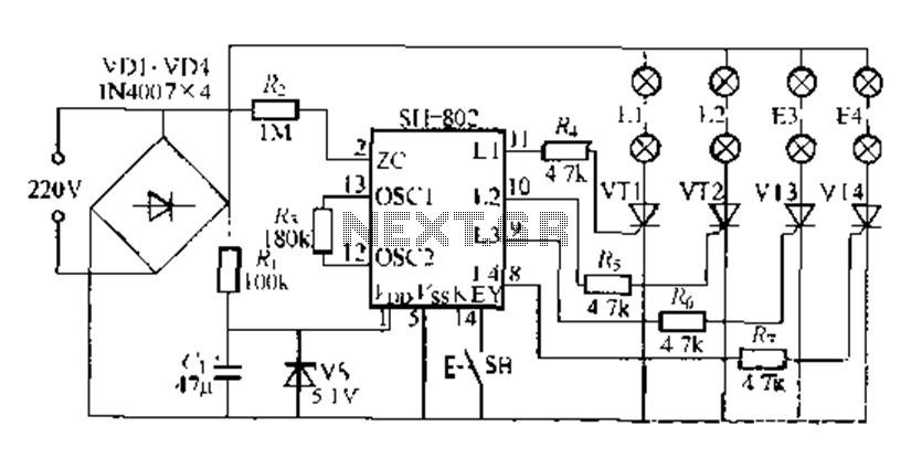
A digital integrated circuit simplifies the response process significantly. The diagram illustrates a circuit comprising four responder groups. The digital integrated circuit described serves as a crucial component in various electronic systems, primarily focusing on enhancing response efficiency. It comprises...

Precision full-wave rectification of differential voltage is achieved by converting voltage to current for rectification and then reconverting to output voltage. One operational amplifier functions as a voltage-to-current converter, while the other serves as a current-to-current rectifier. This circuit...
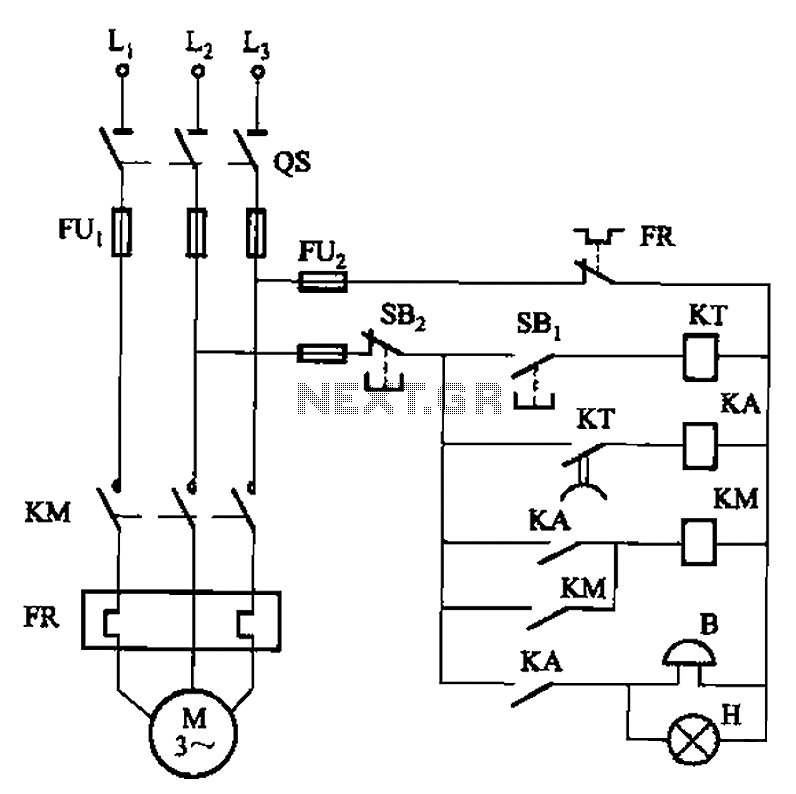
The circuit shown in Figure 3-21 is designed to produce a motor startup sound and a light signal indicating the completion of the startup process, after which the signal ceases. This circuit is tailored to control the motor for...
Warning: include(partials/cookie-banner.php): Failed to open stream: Permission denied in /var/www/html/nextgr/view-circuit.php on line 713
Warning: include(): Failed opening 'partials/cookie-banner.php' for inclusion (include_path='.:/usr/share/php') in /var/www/html/nextgr/view-circuit.php on line 713