
RF Signal Generator
TR1 is a high-gain FET (Field Effect Transistor) configured as a Colpitts oscillator. The oscillation frequency is determined by the variable capacitors (C1 and C2) and five pairs of switched inductors. There is significant overlap between the frequency ranges due to the limited availability of inductors. Even with specially wound inductors, four frequency bands would be required to adequately cover the range. The RF output is buffered by TR2, configured as an emitter follower. The output signal is developed across resistor R6 and passes to the output sockets through variable and switched attenuator circuits. Amplitude modulation is achieved by varying the supply voltage to the oscillator circuit, controlled by TR3, which is also an emitter follower. Capacitor C10 decouples the feed at RF. It is important to note that this modulation method may introduce a small amount of unwanted frequency modulation along with the desired amplitude modulation. This could lead to a slight shrillness in sound if the unit is used for music listening. However, this method does not distort the RF waveform, which is crucial for alignment, and it provides a simpler implementation with consistent results—key requirements for this type of project.
SW2 allows the selection between an internal or external modulation signal. When no modulation is needed, the switch is set to the external position, with no signal applied to SK3. For reasonable modulation, the external signal should be approximately 1.5V RMS (4V peak-to-peak). If a music signal is used, the bandwidth should not exceed about 8 kHz due to AM broadcasting limitations, and C10 will attenuate higher frequencies to some extent. The selected modulation signal is buffered by TR4 and made available on SK4 for triggering an oscilloscope. TR5 is configured in an R-C oscillator circuit, with the frequency set by capacitors C15, C16, C17 and resistors R19, R20, and R21 to around 800 Hz. To modify the frequency, adjustments should be made to the capacitors rather than the resistors, as changing R19 will affect the transistor's biasing. R14 and C13 serve as a filter to eliminate distortion in the output. The circuit operates from a regulated 15V supply, consuming approximately 30 mA. IC1 is a standard three-pin 100 mA regulator, supplied by a full-wave rectified output from a small mains transformer. The audio oscillator requires specific types of capacitors for C15, C16, and C17; ceramic discs have been found suitable, with a 220K resistor for R18 being adequate. Adjustments to the resistor may be necessary to accommodate different transistors. The prototype was built on a plain matrix board, as stripboard is unsuitable due to capacitance between adjacent tracks. A PCB could be designed, following the general layout of the matrix board.This signal generator is intended for realignment of radio receivers. The unit is cheap and fairly basic, but perfectly adequate for its intended purpose. However, the output is not a pure sine wave, so the unit may not be suited for more exacting electronic development work. The unit covers a frequency range of 150KHz to 12MHz over five ranges (s hown below). It is therefore suited to the alignment of RF and IF sections of AM (MW and LW) sets, as well as the IF sections of FM (VHF) circuits. It may also be used for RF alignment of SW circuits from 25 to 49 metres. The output may be amplitude modulated by an internal 800Hz audio tone (approx. 30% modulation) or by an external signal. The output level is adjustable in two ranges up to a maximum of about 4V pk-pk. The unit is mains powered. TR1 is a high gain FET (Field Effect Transistor) and is configured as a Colpitts style oscillator. The oscillation frequency is set by the variable capacitor (C1+C2) and the five pairs of switched inductors.
There is significant overlap between the ranges, due to the limited range of readily available inductors. However even by using specially would inductors, four frequency bands would have been needed to cover the range.
The RF output is buffered by TR2, which is configured as an emitter follower. The output signal is developed across R6, and passes to the output sockets via variable and switched attenuater circuits. The signal is amplitude modulated by varying the supply voltage to the oscillator circuit. This is carried out by TR3, which is an emitter follower. C10 decouples the feed at RF. It should be noted that this modulation method does cause a small amount of unwanted frequency modulation as well as the desired amplitude modulation.
If the unit was being used for listening to music on a radio this could cause a slight shrillness to the sound. However the arrangement has the advantage that it does not distort the RF waveform, which is important for alignment.
It is also simpler to implement and gives consistent results - important requirements for this sort of project. As with any design there are always better ways of doing things, but this would result in a more expensive design that was more difficult to construct, and would not offer any significant advantages in practice.
SW2 selects either the internal or an external modulation signal. If no modulation is required, the switch is set to the external position with no signal applied to SK3. To give reasonable modulation the external signal should be about 1. 5V RMS (4V pk-pk). If a music signal is used, the bandwidth should not extend above about 8KHz due to the limits of AM broadcasting.
C10 will roll-off the higher frequencies to some extent. The selected modulation signal is buffered by TR4 and made available on SK4. This is useful for triggering an oscilloscope. TR5 is configured in an R-C oscillator circuit. The frequency is set by C15, C16, C17, R19, R20 and R21 to about 800Hz. If you wish to alter the frequency, note that altering the value of R19 will affect the biasing of the transistor. Any variations should be carried out by changing the values of the capacitors rather than the resistors.
R14 and C13 act as a filter to remove any distortion on the output. The circuit is powered from a regulated 15V supply, and consumes about 30mA. IC1 is a standard three-pin 100mA regulator, fed by the full-wave rectified supply from a small mains transformer. The audio oscillator is quite particular about the types of capacitor used for C15, 16 and 17. I used ceramic discs - and with these 220K for R18 was fine. Maybe the resistor needs to be adjusted to suit the transistor used The prototype was constructed on a piece of plain matrix board.
Stripboard is not suitable because of the capacitance between adjacent tracks. A PCB could be designed, but this should follow the same general layout as the matrix board. In the diagra 🔗 External reference
Related Circuits
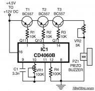
This is a simple home telephone ringtone generator circuit constructed using only a few electronic components. It generates a simulated telephone ringtone and requires a DC supply voltage ranging from 4.5V to 12V. This circuit can be used in...
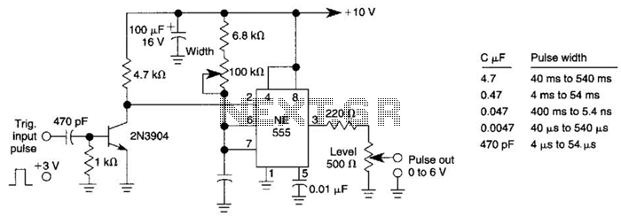
This pulse generator can enhance a standalone pulse generator. By utilizing a transistor and a 555 timer, it can produce pulse widths ranging from 5 microseconds to 500 microseconds. The value of capacitor C3 can be approximately determined using...
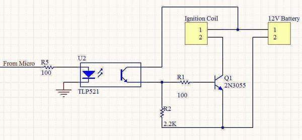
A 12V motorcycle battery and a car ignition coil are utilized in this project. A microcontroller generates pulses to the base of a 2N3055 transistor, which switches the primary of the ignition coil on and off, producing the desired...
This circuit generates sine, square, and triangle waves ranging from 0.1 Hz to 1 MHz. It includes a counter that measures the frequency of the function generator or an external signal with a peak-to-peak voltage of a few volts,...
Power input is to a 7805 5 volt regulator. A pair of LEDs is connected between the 5 volt supply and ground, with current limiting resistors in series and one pin on the AT90S2313 shunts the current through one...
This circuit design for a high-frequency waveform generator is highly beneficial for electronic experiments and designs. The circuit generates sine wave oscillations, but it can also be modified to produce triangle or square wave functions. The high-frequency waveform generator circuit...
Warning: include(partials/cookie-banner.php): Failed to open stream: Permission denied in /var/www/html/nextgr/view-circuit.php on line 713
Warning: include(): Failed opening 'partials/cookie-banner.php' for inclusion (include_path='.:/usr/share/php') in /var/www/html/nextgr/view-circuit.php on line 713