
Signal Generator 20KHz
The function generator described operates within a frequency range up to 20 MHz, although practical usage has been observed to be effective up to 50 kHz. This device utilizes an integrated circuit (IC) that can generate various waveforms, typically sine, square, and triangle waves, essential for testing and development in electronic applications.
Two primary methods are employed for frequency control. The first method involves manual adjustment of the control voltage supplied to the IC. This method requires the user to interact with a control knob while monitoring the frequency output on a connected counter. However, this approach can be cumbersome, as the display updates occur only once per second, leading to potential inaccuracies during fine-tuning.
The second method enhances usability by automating the control process. In this configuration, the user sets the desired frequency using the control knob, and the circuit automatically adjusts the control voltage to the IC to achieve the target frequency. This is accomplished by calculating the required period for the desired frequency and utilizing a PIC (Programmable Interface Controller) to measure the pulse width of the output signal. The PIC then generates short correction pulses that are sent to an integrator circuit, which modulates the control voltage to stabilize the output frequency.
The integration of a PIC allows for a more responsive and accurate frequency adjustment, minimizing the need for manual intervention and streamlining the operation of the function generator. The inclusion of source, object, and schematic files indicates that the design may be open for further development, allowing users to modify or enhance the functionality of the circuit as needed.This fucntion gernerator IC is specified to work to 20 MHz. So far, this unit works nicely to 50KHz. Since I seldom need signals higher than that, it has taken up a happy home on my workbench and further development is iffy at best. There are two basic approaches to controlling the frequency in this type of device. One way is to adjust the voltage to the IC manually and then read out the frequency with a counter. The problem here is you need to fiddle around with the control knob and while waiting for the one-per-second updates on the display.
The other way is to set the display with the control knob and then have the circuit diddle the control voltage to the IC until it settles on that frequency. This is done by calculating the period for the target frequency and then using the PIC to read the pulse width.
It then sends short correction pulses to an integrator which controls the IC. For your edification and amusement here are the Souce, Object, and Schematic files. 🔗 External reference
Related Circuits
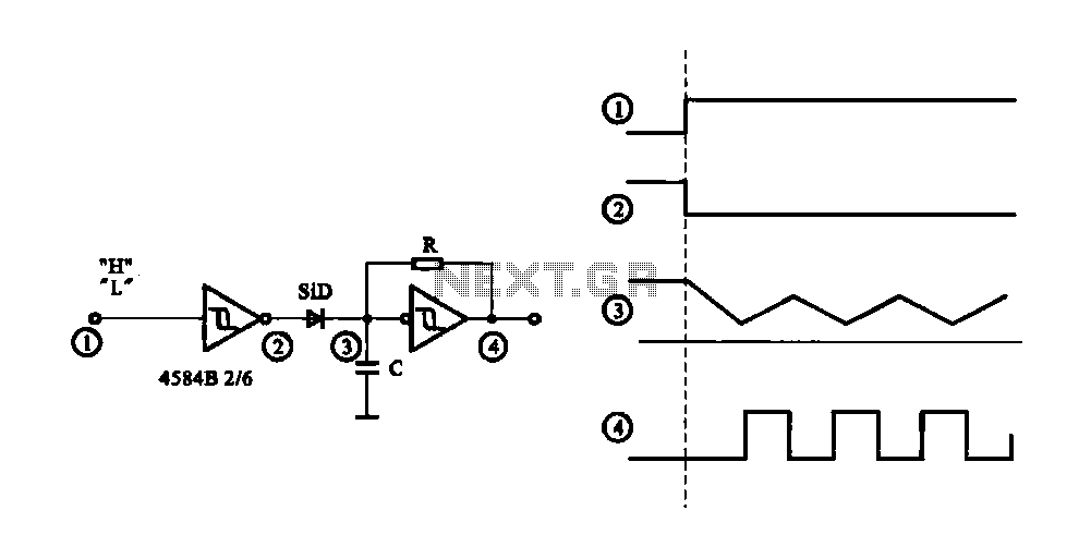
The circuit generates a controlled pulse signal. When a high pulse signal is applied to the input terminal O (start), the output pulse signal is activated. Conversely, when a low signal is received at the input terminal O (stop),...
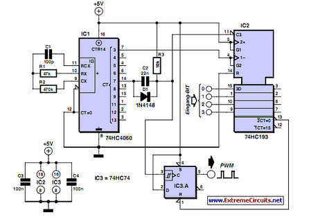
PWM waveforms are frequently utilized to regulate the speed of DC motors. The duty cycle of the digital waveform can be defined using an adjustable parameter. PWM (Pulse Width Modulation) is a technique employed to control the power delivered to...
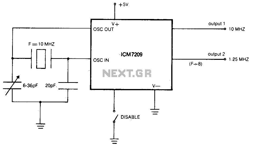
The CMOS IC directly drives five TTL loads from either of two buffered outputs. The device operates at up to 10 MHz and is compatible with bipolar, MOS, and CMOS technologies. The CMOS integrated circuit (IC) is designed to interface...
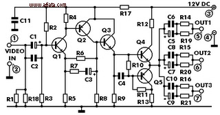
This electronic circuit is a video signal amplifier that provides a broad bandwidth amplifier with a capacity of 5 MHz. It is designed to take video signals from a VCR and amplify them adequately to drive up to three...
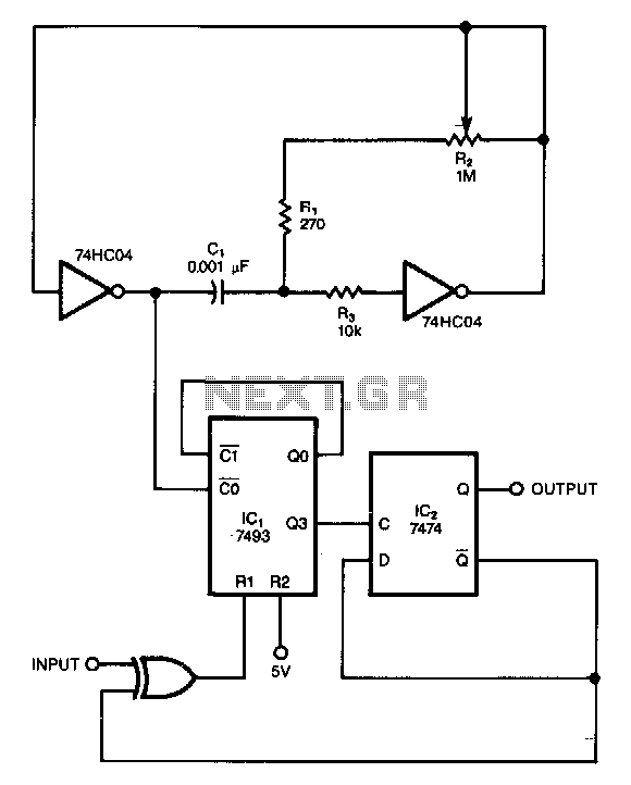
This circuit filters noise, such as glitches and contact bounce, from digital signals. It can be easily adjusted for a wide range of noise frequencies. The circuit's output changes state only if the input differs from the output long...
How to create a hydrogen generator using a 555 timer circuit with Pulse Width Modulation (PWM). This PWM circuit can generate hydrogen on demand. The hydrogen generator circuit utilizing a 555 timer operates by controlling the duty cycle of the...