
Five-way operation of the dynamic braking circuit

The circuit operates by discharging a capacitor to provide a controlled braking action for small motors. When the motor is to be stopped, the capacitor C is discharged through the relay KA, which is activated by the circuit control mechanism. The energy stored in capacitor C is released, creating a braking force that slows down the motor.
The relay KA plays a crucial role in this circuit by controlling the discharge path of the capacitor. The resistance of the relay coil affects the timing of the relay's activation and, consequently, the braking duration. By adjusting the resistance and the capacitance values, the user can tailor the braking performance to meet specific requirements of the application.
Capacitor C must be selected based on the required braking time and the characteristics of the motor. Larger capacitance values will result in longer braking times, while smaller values will decrease the duration. The release current of the relay KA must also be considered, as it determines how quickly the relay can disengage after braking is initiated.
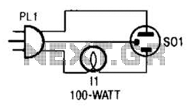
This circuit configuration is particularly beneficial for applications where a transformer is impractical or where space and cost savings are desired. The energy storage capacitor discharge method provides an efficient and effective means of controlling motor braking without the complexity of additional transformer components. Circuit shown in Figure 3-137. This eliminates the need for a step-down transformer line, using the principle of energy storage capacitor discharge realization brake, it can be used to transform infrequent power llkW less motor. Braking length of time, depending on the relay KA coil resistance, capacitance C of capacity and KA release current adjustable capacitor C general capacity to alter the length of the braking time.
Related Circuits
The tester provides an audible indication of the logic level of the signal presented to its input. A logic high is indicated by a high tone, a logic low is indicated by a low tone, and oscillation is indicated...
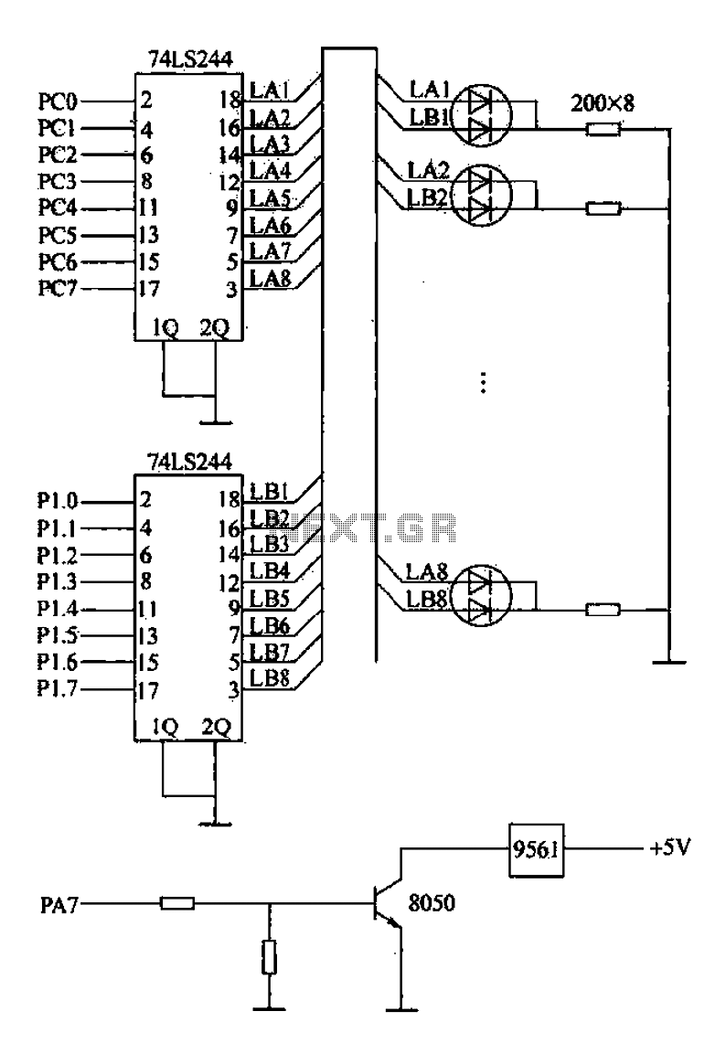
Alarm interface circuitry featuring a two-color light-emitting diode (LED) display. When LAi is at a high level and LBi is low, the green LED lights up; conversely, if LAi is low and LBi is high, the red LED lights...
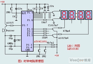
The circuit design incorporates an anodic Nixie tube for the LED display. It utilizes the LQ5101BS general luminous diode, with the driving transistor being either the 2SA1015 or 2SC1815 types, which are readily available. Additionally, low-power transistors such as...

The BFP640 transistor is utilized for 1575 MHz Global Positioning Satellite (GPS) applications, specifically as a Low Noise Amplifier (LNA). The design objectives include a minimum gain of 16 dB, a noise figure of less than 0.6 dB, an...

RS-232 Serial Interface Status Indicator Circuit. This circuit utilizes a single logic integrated circuit (IC) to indicate the transmission (TXD) and reception (RXD) statuses of a serial interface. The RS-232 Serial Interface Status Indicator Circuit is designed to provide visual...

This simple mock flasher LED simulates the indicator of a sophisticated alarm system. It can be placed in doors, gates, and vehicles to confuse intruders. The mock flasher LED circuit is designed to mimic the flashing behavior of a typical...