
Circuit converts pulse width to voltage
The circuit described utilizes two LT1880 operational amplifiers (IC2 and IC3) which are characterized by their low input bias current, making them suitable for applications where precision is critical. The first op-amp (IC2) is configured as an integrator. This configuration allows the circuit to integrate the incoming pulse signal over time, effectively converting the pulse's area under the curve into a corresponding voltage level. The integration process is crucial for transforming pulse information into a smooth DC voltage that represents the average value of the input signal.
The LTC202 quad analog switch (IC1A, IC1B, IC1C, and IC1D) plays a vital role in the sampling and holding stages of the circuit. These switches enable the circuit to sample the voltage level produced by the integrator at a specific moment in time, effectively capturing the voltage corresponding to the end of the incoming pulse. The sample-and-hold functionality ensures that the output voltage remains stable and does not fluctuate as the input signal changes.
The use of an RC filter can also be noted as an alternative method for converting PWM signals into an averaged DC voltage. However, this method is slower in terms of response time and may not be suitable for applications requiring rapid changes in the input signal. Furthermore, the circuit's ability to convert low-duty-cycle pulse information is limited, as the response time decreases with shorter pulse widths.
Overall, the combination of the LT1880 op-amps and the LTC202 analog switches creates a robust circuit capable of accurately converting pulse information into a clean DC voltage, making it suitable for various applications in signal processing and control systems.The circuit in Figure 1 converts pulse information to a clean dc voltage by the end of a single incoming pulse. In another technique, an RC filter can convert a PWM signal to an averaged dc voltage, but this method is slow in responding.
Converting low-duty-cycle pulse information is slower yet.
The circuit in Figure 1 uses two low-input-biascurrent LT1880 op amps, IC2 and IC3, and an LTC202 quad analog switch, IC1A, IC1B, IC1C, and IC1D, to configure the integrator and sampleand- hold stages that convert a single pulse to a dc voltage. Th
🔗 External referenceRelated Circuits
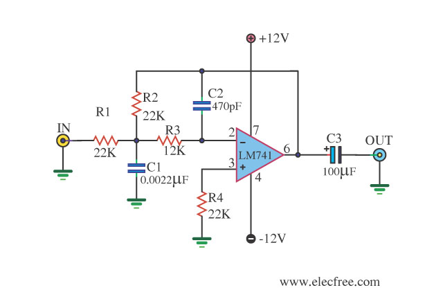
This circuit filters low frequencies below 10 kHz using the highly popular operational amplifier IC uA741. It is convenient for applications that require the conversion of analog signals to digital or vice versa. In digital sound systems, this circuit...
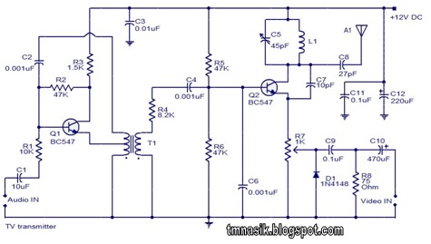
The TV transmitter circuit described utilizes UK standard 1 FM modulation for audio and PAL modulation for video. The audio signal intended for modulation is first amplified using transistor Q1 and its associated components. Transistor Q2 serves dual purposes:...

One way to provide effective negative-voltage regulation is by using a low-dropout positive-voltage regulator operating from a well-isolated secondary winding of a switch-mode circuit transformer. This technique is applicable to any positive-voltage regulator, although the highest efficiency is achieved...
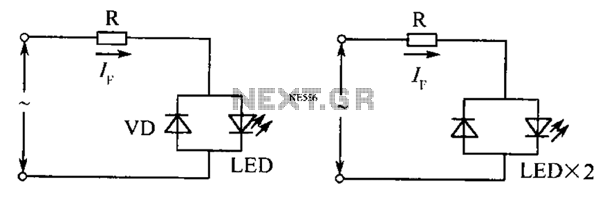
The circuit operates effectively even when the polarity of the voltage or the power supply is reversed. It functions with DC drives similar to AC drives, utilizing a current limiting resistor R. The value of this resistor is determined...
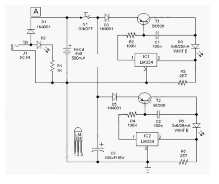
This easy-to-construct "Handy Pen Torch" electronic circuit has a low component count and utilizes two power white LEDs for lighting. It operates on a low voltage supply of 4.8V DC. The Handy Pen Torch circuit is designed to provide a...
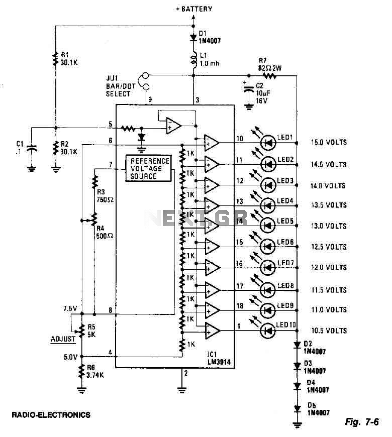
This screen utilizes ten LEDs to indicate a voltage range from 10.5 to 15 volts, with each LED corresponding to a 0.5-volt increment. The core component of the circuit is the LM3914 LED bar graph/display driver. A trimming potentiometer,...
Warning: include(partials/cookie-banner.php): Failed to open stream: Permission denied in /var/www/html/nextgr/view-circuit.php on line 713
Warning: include(): Failed opening 'partials/cookie-banner.php' for inclusion (include_path='.:/usr/share/php') in /var/www/html/nextgr/view-circuit.php on line 713