
25W HiFi Audio Amplifier with MOSFET

The high-fidelity audio amplifier circuit is designed to deliver superior sound quality without the need for an additional pre-amplifier stage. This simplicity in design allows for a more direct signal path, which can contribute to enhanced audio performance.
The circuit utilizes a combination of resistors to set the gain and manage the input and output levels effectively. The resistors specified in the component list include:
- R1 and R4, each rated at 47K ohms and 1/4 watt, which are likely used in the feedback loop to stabilize the amplifier's gain.
- R2, with a resistance of 4.7K ohms, serves to set the input impedance, ensuring compatibility with a variety of audio sources.
- R3, a 1.5K ohm resistor, may be used to control the biasing of the amplifier stage, optimizing the operation of the active devices within the circuit.
- R5 and R6, rated at 390 ohms and 470 ohms respectively, are used to manage current flow and protect the circuit from excessive power dissipation.
The choice of 1/4 watt resistors indicates that this circuit is designed for moderate power applications, suitable for driving small to medium loads without significant thermal concerns. The overall design emphasizes high fidelity, making it ideal for audiophiles seeking to reproduce sound with minimal distortion.
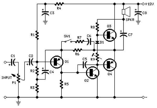
In summary, this audio amplifier circuit is a straightforward yet effective solution for achieving high-quality sound reproduction, utilizing a carefully selected array of resistors to optimize performance and reliability.This is high fidelity, high quality audio amplifier circuit diagram. You dont need pre amplifier. Component list: R1,R4 = 47K 1/4W Resistors R2 = 4K7 1/4W Resistors R3 = 1K5 1/4W Resistors R5 = 390R 1/4W Resistors R6 = 470R 1/4W Resistors R.. 🔗 External reference
Related Circuits
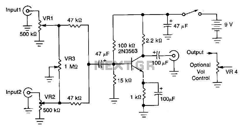
This circuit mixer features internal amplification using a 2N3563 transistor. Two input signals can be independently adjusted via VRI and VR2. The VR3 balance control allows for the attenuation of one signal while the other remains active. Additionally, the...
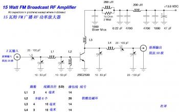
This is a high-quality FM transmitter suitable for use with stereo systems or other amplifiers, providing a strong signal strength with a range of up to 500 meters and a power output of approximately 200 mW. The circuit operates...
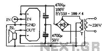
The D amplifier utilizes a series fool manifold and can easily be configured as a mono output transformerless (OTL) or output capacitorless (OCL) audio power amplifier. Figure 3-12 illustrates a single-channel power output typical application wiring diagram for OTL....
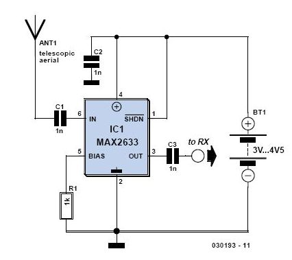
This is a high-performance radio receiver antenna amplifier designed for the entire VHF broadcast and PMR band (100-175 MHz) that can be successfully constructed without... This radio receiver antenna amplifier is engineered to enhance the signal quality and reception capabilities...
The circuit is intentionally designed using older type transistors to achieve harmonic distortion and to mitigate the challenges of sourcing high-quality components. The amplifiers can be easily powered by a plug-in wall transformer rated at 12V. When SW1 is...
A straightforward 4-channel video amplifier electronic circuit can be constructed using the NJM2582 integrated circuit, which is suitable for video applications with a SCART connector. The design of this circuit is uncomplicated and requires only a few external electronic...