
silicon fuzz
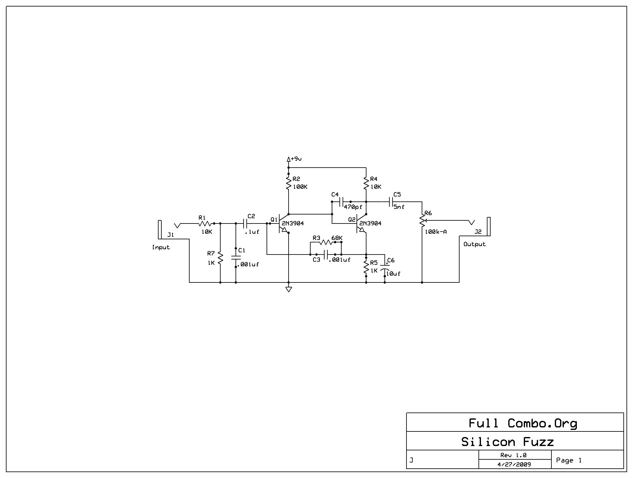
The Mighty Mite amplifier and the fuzz face circuit together create a unique audio experience, blending the clean amplification of the guitar signal with the rich, textured distortion of the fuzz face. The schematic for the fuzz face typically includes two stages of amplification, each utilizing an NPN transistor configuration. The first transistor amplifies the input signal, while the second transistor further boosts the signal before it is sent to the output. Capacitors are strategically placed to filter out unwanted frequencies, ensuring that only the desired harmonics are produced.
In this configuration, the input signal from the guitar is fed into the base of the first transistor, which is configured in a common emitter arrangement. This arrangement provides voltage gain and inverts the signal. The collector of the first transistor is connected to the base of the second transistor, allowing it to amplify the already boosted signal further. The output of the second transistor is then coupled through a capacitor to the output jack, where it can be sent to an amplifier or effects chain.
Additionally, resistors are employed to set the biasing conditions for each transistor, ensuring they operate within their optimal range. The choice of resistors and capacitors can significantly influence the tonal characteristics of the fuzz face, allowing for various modifications to achieve the desired sound.
In summary, the integration of the Mighty Mite amplifier with a fuzz face circuit constructed from salvaged components exemplifies the principles of DIY electronics and the enduring appeal of classic audio effects. The careful selection of transistors, along with strategic component placement, culminates in a versatile and powerful fuzz effect that pays homage to its roots in rock music history.After building the Mighty Mite amplifier project, I found that it needed something extra to give it character. I thought a nice Hendrix-style fuzz face would add a nice edge to the tone as well as allow some character to come along with low-volume playing.
Well, what a universe unfolded when I started researching the internal workings of this devi ce. It is perhaps the perfect example of seeming simplicity masking amazing nuance and system complexity. The damn thing is just two NPN transistors and a few caps and resistors! However, you can spend days 1) trying to figure out how the circuit works and 2) weeks/months combing through the mountain of information on the net about components, modifications, what sounds good, what sounds bad, etc.
I made it my goal to understand this enigma and build a good-sounding fuzz box out of 100% scrap and on-hand parts. No trip to the store, no expense. Nothing but some previously junk-parts and some wire and solder. Much of the wind that has been expelled about the fuzz face is about the transistors in use. Note that the fuzz face is a very old device. It is said that the Rolling Stones (I Can`t Get No) Satisfaction started the whole distortion/fuzz trend that quickly became the standard for Rock guitar.
As early as 1968, hobbyist projects and articles in Popular Electronics were guiding the DIY crowd in building this simple device. That`s probably where the controversy started. Back in that day, transistors were made from a magical substance called Germanium This naturally occurring mineral was discovered to have semi-conductor properties when the Germanium crystals were "doped" or otherwise mixed with slight impurities.
Soon Silicon replaced Germanium for several reasons including cost, manufacturability, and thermal stability. However, early electronics, especially audio circuits, were optimized around certain aspects (peculiarities, you might say) of Germanium.
The two-transistor Fuzz Box is probably both the most optimized AND peculiar of any design. Most current DiY fuzz projects insist that proper tone can only be had with the low-gain, leaky collector->base junction Germanium transistors. All of the parts stores seem to have a stash of these and dole them out at pretty high prices. When a design stoops to use a modern silicon transistor design, it is usually also accompanied by a disclaimer that this design sounds "Ok" but clearly not as good as a Ge based design.
Ok, well. let me get this straight. We`re designing a circuit that takes the nice modal sine-wave output of an electric guitar and overdrives this signal until it more resembles a square wave with some RC constant wavefront shapes thrown in for good measure. The output of this wave is described as shredded and about to tear your speakers apart. and we`re concerned about quality of the transistors Actually, I say the above somewhat in jest because there is a concern about the gain of these transistors and the operation of the circuit.
It is a fact that today`s Si transistors are much more efficient and produce much higher current gain that the Ge devices from before. That`s why when you see a silicon transistor fuzz circuit today, most of the design tweaks are about mitigating the high gain.
Couple this with the ease of building a fuzz box and you can begin to understand why there are so many different designs and tweaks for basically the same design that Dallas Arbiter unleashed upon the world more than forty years ago. In keeping with my frugality quest, I decided to use the transistors that were soldered into a scrapped Zircon Stud Finder that I had in my scrap box.
As luck would have it, there were two very nice 2N3904 devices as well as a bunch of salvageable caps just waiting to be de-soldered and re-used. The current gain of the 2N3904 varies with collector current and voltage but in this application it should provide a current gain of about 150.
That soun 🔗 External reference
Related Circuits
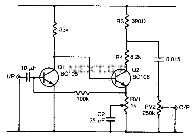
Q1 and Q2 form a voltage amplifier that provides sufficient gain to be overdriven by a relatively low input, such as an electric guitar. The output from Q2 is a squared-off version of the input, resulting in the desired...
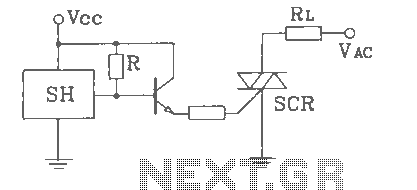
SH Hall opened with a double silicon output interface circuit The SH Hall sensor circuit is designed to provide a dual silicon output interface, which enables enhanced signal processing capabilities. This circuit typically integrates a Hall effect sensor that detects...

This circuit was designed to obtain a valve-like distorted sound from an electric guitar or other musical instrument. For this purpose a very high gain, three-FET amplifier circuit, was used. The output square wave shows marked rounded corners, typical...

Doug Grant's article on Heathkit in his blog via the EDN Network reflects on his experience building his first Heathkit and the knowledge he gained. He suggests that every electrical engineer has built at least one kit, a notion...
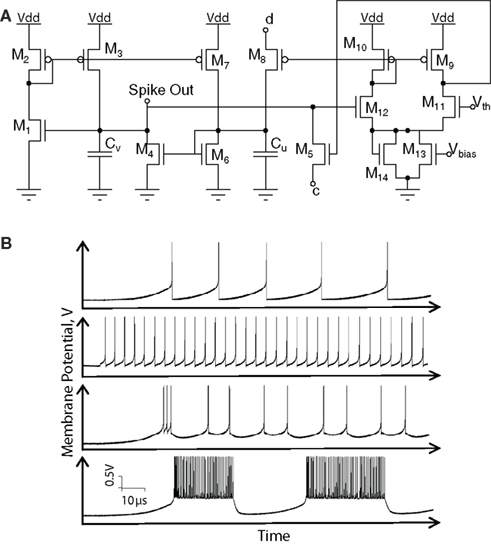
Hardware implementations of spiking neurons are highly beneficial for various applications, including high-speed modeling of large-scale neural systems, real-time operating systems, and bidirectional brain-machine interfaces. The specific circuit solutions for silicon neurons are dictated by the requirements of each...
This guitar effect circuit employs a straightforward high-gain amplification stage, succeeded by symmetric clipping achieved through a parallel diode clipper. The gain is provided by a 741 operational amplifier. The circuit design begins with a high-gain amplification stage utilizing the...