
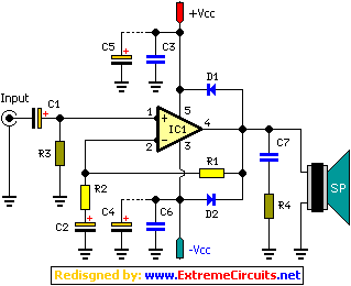
Silicon photocell remote control circuit

The circuit begins with the primary input of 220V AC, which is stepped down to 19V AC by transformer T. This transformer is essential in ensuring that the voltage level is safe and suitable for the subsequent rectification process. Following the transformer, the AC voltage is converted to pulsating DC using a full-wave bridge rectifier, which consists of four diodes arranged in a bridge configuration. This rectification process allows both halves of the AC waveform to contribute to the output, resulting in a smoother DC voltage.
The output from the bridge rectifier is then smoothed out by a filter capacitor, denoted as C. This capacitor serves to reduce the ripple voltage, providing a more stable DC output. The filtered voltage is then fed into a 7812 voltage regulator, which is designed to output a consistent 12V DC. This regulator is crucial for powering sensitive electronic components that require a stable voltage for proper operation.
The circuit incorporates a battery indicator light, which serves as a visual cue that the system is operational. When this light is illuminated, it signifies that the circuit is in a monostable or bistable state. In a monostable configuration, the circuit can toggle between a stable state and a temporary active state. Conversely, in a bistable configuration, the circuit can maintain two stable states, allowing for more complex control mechanisms.
The operational state of the circuit can change, allowing it to connect or disconnect the electrical load path. This is typically achieved through a thyristor, which acts as a switch that can be turned on or off to control the power delivered to lighting or household appliances. The thyristor is triggered based on the circuit's state, enabling efficient control over the connected load, thereby enhancing the overall functionality of the system. This arrangement provides a robust solution for managing electrical loads in various applications, ensuring both safety and reliability.220V AC voltage through the transformer T transformer is 19V, after full-wave bridge rectifier, filter capacitor c], terminal regulator blocks 7812 after regulators into DC vol tage. When the battery light is lit the monostable state or bistable circuit flip. Changing the operating state of the circuit, to connect or disconnect the electrical load path, or thyristor trigger circuit is turned on, the control switch lighting or household appliances.
Related Circuits
A 2 x 18W Hi-Fi Stereo Power Amplifier is designed using two TDA2030 integrated circuits (ICs). This amplifier features excellent input sensitivity, low distortion levels, stable operation, and comprehensive protection against overloads and output short circuits. It can serve...

Manufacturer of thermoelectric materials, custom thermoelectric coolers, and value-added thermal assemblies. The manufacturer specializes in the development and production of thermoelectric materials, which are essential for converting temperature differences into electric voltage and vice versa. These materials are utilized in...
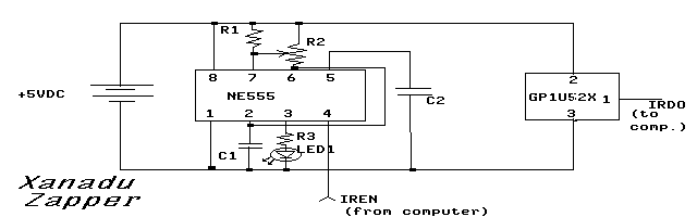
This article provides insights on how to interface infrared (IR) remote controllers with a computer. Possible applications include controlling a computer using a TV remote or managing a VCR through a computer. The circuit discussed was initially shared in...
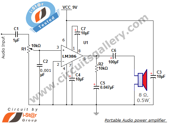
The i-St@r presents a simple mini audio amplifier circuit schematic utilizing the LM386 low voltage audio power amplifier IC. This circuit is designed to power medium-sized speakers from a music player that typically drives only earphones (LM386 headphone). The...
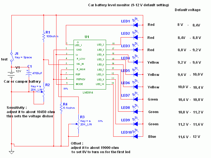
This circuit utilizes the widely available LM3914 integrated circuit (IC). The IC is straightforward to operate, does not require external voltage regulators due to its built-in voltage regulation feature, and can be powered from nearly any voltage source. The LM3914...
The core component of this circuit is the 555 timer IC. The alert sound does not stop immediately when the switch is activated; instead, it ceases automatically after a predetermined time period, which is set by the resistance of...