
RF 433MHz - 3 channels remote control
The described circuit operates as a remote-controlled system utilizing a Nutchip microcontroller and a radio receiver. The primary function of the circuit is to control three outputs through a set of buttons on a remote control. The Nutchip is connected to three driving transistors, which in turn control the operation of three separate output devices, indicated as output 1, output 2, and output 3.
The radio receiver receives commands from the remote control, with the data being transmitted from the OUT pin of the receiver to the REMOTE pin on the Nutchip. The circuit includes a RESET pin connected to an external resistor-capacitor (RC) delay circuit, which is crucial for maintaining uninterrupted service in environments with electrical noise. For optimal performance, especially in electrically polluted environments, it is recommended to utilize a specialized RESET circuit.
Unused input pins on the Nutchip are connected to a positive voltage, a practice that helps mitigate potential interference and ensures stable operation. Capacitors C2 and C3 are strategically placed close to the receiver terminals to filter out any radio frequency interference, with short leads to the ground to minimize inductive effects.
The circuit is designed to operate at a nominal voltage of 5 volts. However, it is adaptable to a 12-volt power supply if necessary. In such cases, the connection to the +5 volts terminal can be removed, allowing for the integration of a 12-volt power supply without issues.
The remote control features six keys, each assigned specific functions to control the outputs. Key1 activates output 1, Key2 activates output 2, and Key3 activates output 3. Conversely, Key4, Key5, and Key6 are designated to deactivate outputs 1, 2, and 3, respectively. The system can exist in eight distinct states, each representing a unique combination of outputs being activated or deactivated. For instance, in state ST03, outputs 1 and 2 are active, while output 3 is inactive. The user can manipulate the outputs by pressing the corresponding keys to achieve the desired configuration. This design allows for versatile control over multiple devices, making it suitable for various applications requiring remote operation.The schematic is very simple and includes, in addition to Nutchip, with its three driving transistor and LED, the radio receiver. The data come from the OUT pin of the receiver and enter the pin REMOTE remote control. The RESET pin connected to an external RC delay. If you need to mount the telecomandodove is required uninterrupted service 24 hours on 24 or in electrically polluted environments sar?
then best to use a special built for RESET. Notice that the unused input pins are connected to the positive: a good habit that makes life difficult for disorders. Even the capacitors C2 and C3 are used to "clean up" the voltage from any radio interference that slip into the receiver must be mounted as close as possible to the terminals of receiver, with wires short to ground.
The entire circuit is powered at 5 volts, including. Since the 12 volt are still readily available you might want to mount them in place of 5 volts, in which case no problem, detach the terminal baster? rel? that goes to the +5 volts to link them to a power supply that also provides the 12 volts. You must first determine which buttons are used to turn on the outputs and what to turn off. We decided that the keys are assigned the following functions: key1: turn on output 1 key2: turn on output 2 key3: Turns out the 3 Key4: Exit 1 off key5: Highway exit off the 2 KEY6: Exit 3 off The table of the states of this remote control has eight states: virtually any combination of outputs corresponds to a state.
For each state there are only three possible conditions: imagine you are in such state ST03. Reading the corresponding outputs in this state on the table, we find that the first and second exit will be on, the third meter energized. Under these conditions we can: Key4 press to turn off the first exit key5 press to turn off the second exit key3 press to turn the third exit.
🔗 External reference
Related Circuits
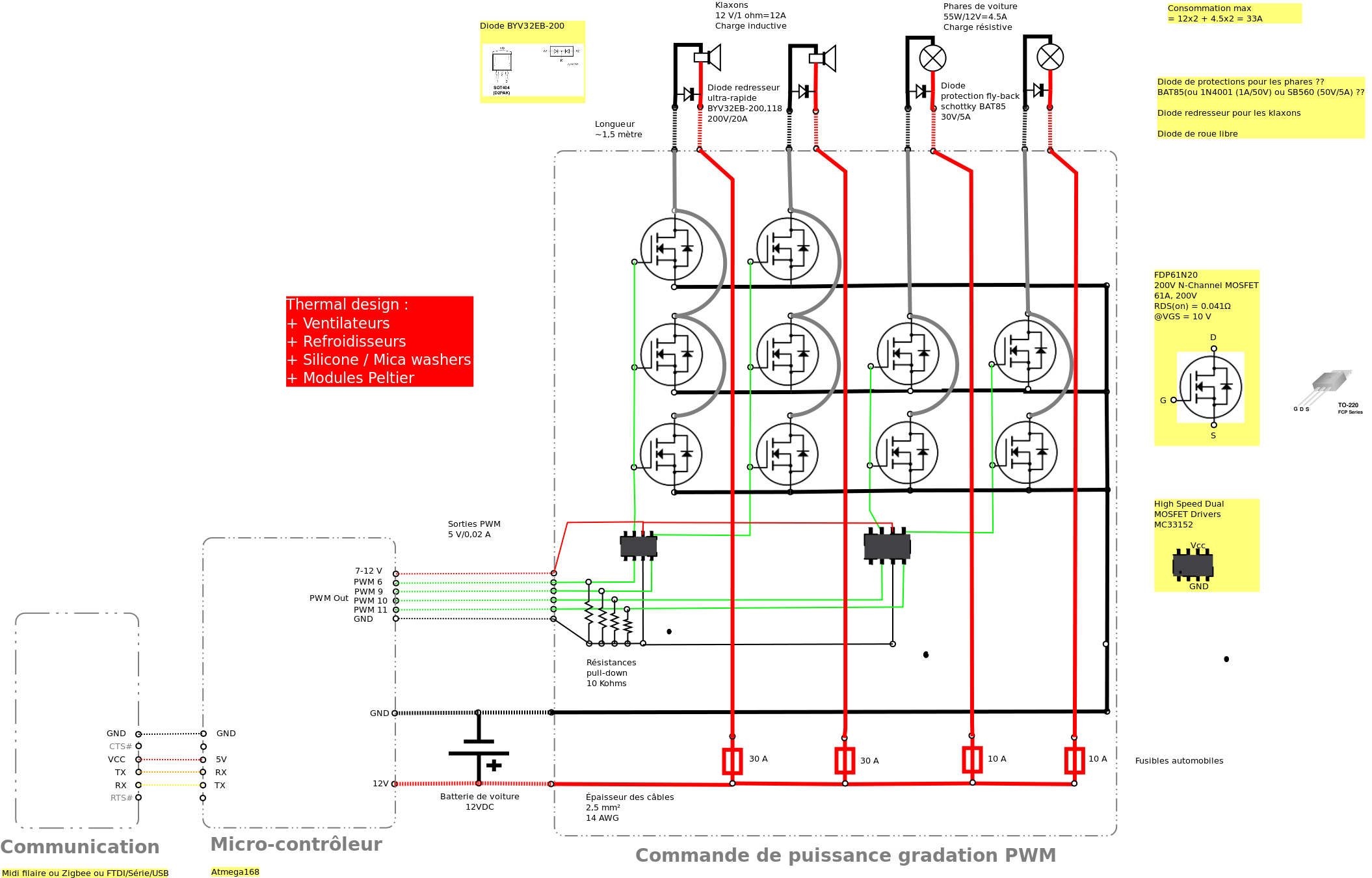
Past experiences were quite challenging due to the inductive nature of car horns, which require 12A of current, with peak demands reaching 20 to 30A. The current electronic system lacks reliability, given the high intensity. There is a need...
The following circuit illustrates the AT90LS2323 Microcontroller Circuit Diagram. Features include a voltage range of 2.7 to 6 volts, and compatibility with all 2323 chips. Components are included. The AT90LS2323 microcontroller circuit is designed to operate within a voltage range...
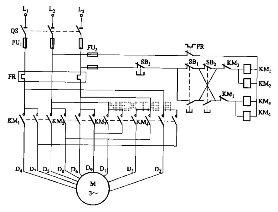
The circuit depicted in Figure 3-112 features two operation buttons: SBi, which serves as the first speed operation button, and SBz, which operates the second speed class. Both buttons facilitate two speeds in the same direction. The circuit design incorporates...
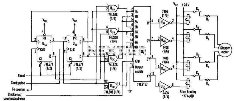
This new circuit utilizes four integrated circuits, with the option to operate with just three by combining the flip-flops and AND gates. The frequency of clock pulses dictates the revolutions per minute (RPM) of the motor. The circuit can...
This voltage-controlled oscillator circuit is compact and exhibits good linearity. The precision can be better than 0.01% if properly constructed. The circuit provides three different output waveforms: square, triangle, and sawtooth, which are essential for music synthesizers and measurement...
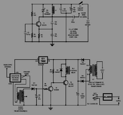
This circuit of an FM radio-controlled anti-theft alarm can be utilized with any vehicle that has a 6 to 12-volt DC supply system. The mini VHF FM transmitter is installed in the vehicle during the night when it is...