
Alarm Circuit Using Keypad

The alarm circuit described utilizes a keypad interface for user interaction, allowing for a versatile and secure alarm system. The selection of a BC547 transistor as the core component ensures sufficient current handling and switching capabilities for the application. The design employs a matrix keypad configuration, which optimizes the number of connections needed while allowing for a large number of possible combinations for user codes.
The operation begins when the user presses key `E`, which initiates the alarm sequence. The current flow through diode D2 and resistor R9 is crucial, as it activates the transistor Q5. This transistor acts as a switch for the relay, which is responsible for controlling the output state of the alarm system. The relay's ability to maintain its state via resistor R10 is a key feature, allowing the alarm to remain active even after the initial key press.
The circuit's design incorporates a series of gates that work sequentially to ensure that only the correct code can deactivate the alarm. Each gate locks itself on, creating a cascading effect that requires precise input from the user. This method not only adds complexity to the code entry process but also enhances security by making it more difficult for unauthorized users to disable the alarm.
Additionally, the flexibility of the circuit is evident in its ability to change the code by simply altering the connections of the keypad. This feature allows for easy updates to the security protocol without needing significant modifications to the circuit itself. The suggestion to use a larger keypad with more potential "wrong" keys connected to terminal `F` further emphasizes the design's adaptability and focus on security.
Overall, this alarm circuit design provides a practical solution for security applications, combining user-friendly operation with robust electronic components to ensure reliability and effectiveness in alarm management.This is a design circuit for alarm circuit. This circuit is controlled by keypad. For the core of the circuit is using a single transistor with BC547 series. This is the figure of the circuit. For operation, on a 12-key pad, look for 13 terminals. The matrix type with 7 terminals will NOT do. The Alarm is set by pressing a single key. Choose the k ey you want to use and wire it to `E`. Choose the four keys you want to use to switch the alarm off, and connect them to `A B C & D`. Your code can include the non-numeric symbols. With a 12-key pad, over 10 000 different codes are available. Wire the common to R1 and all the remaining keys to `F`. When `E` is pressed, current through D2 and R9 switches Q5 on. The relay energizes, and then holds itself on by providing base current for Q5 through R10. The 12-volt output is switched from the "off" to the "set" terminal, and the LED lights. It locks itself high using R2 and it enables gate 2 by taking pin 5 high. The remaining gates operate in the same way, each locking itself on through a resistor and enabling its successor. If the correct code is entered, pin 10 will switch Q4 on and so connect the base of Q5 to ground. This removes the `enable` from gate 1, and the code entry process fails. If `C` or `D` is pressed out of sequence, Q1 or Q2 will also take pin 1 low, with the same result. You can change the code by altering the keypad connections. If you need a more secure code use a bigger keypad with more `wrong` keys wired to `F`. 🔗 External reference
Related Circuits
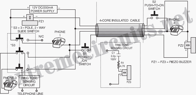
The circuit described can connect two telephones in parallel and function as a two-line intercom. Typically, a single telephone is connected to a telephone line. When another telephone is needed at a distance, a parallel line is utilized for...

This second-order low-pass filter utilizes a 741 operational amplifier and can be tuned from 2.5 kHz to 25 kHz. The circuit is beneficial in audio and tone control applications. R1 and R2 are ganged potentiometers. The described circuit features a...
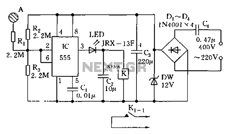
The touch sensor switch circuit diagram features a step-down rectifier circuit, a 555 timer, and flip-flops. When a hand touches the metal sheet A, the sensor signal activates the internal comparator of the 555 timer, setting the output to...
That circuit is based at a technique to remove or neutralize the salt in water, and protect the pipes at home as well as the washing machines or our selves from salt. Its called water softener and its automated...
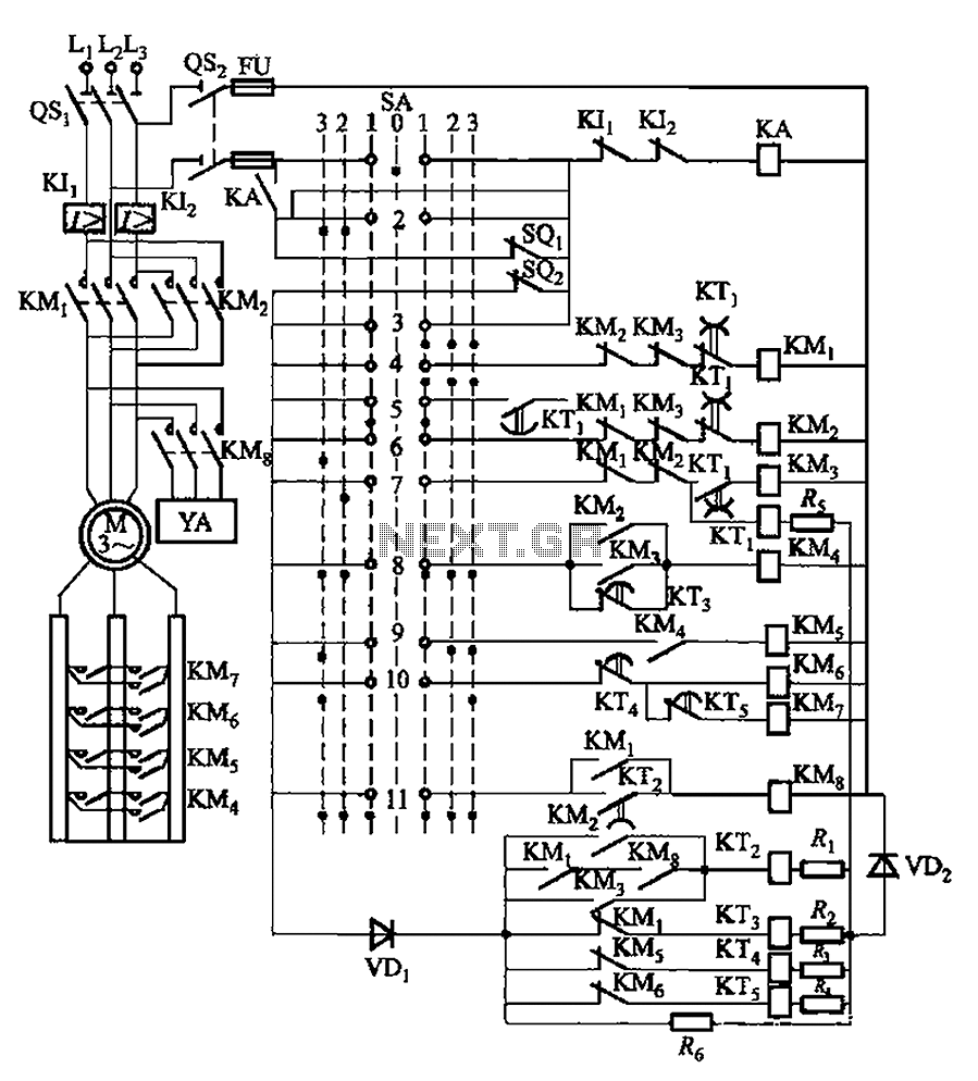
The system involves a master controller and a PQS1 Series Magnetic control panel, which includes a control circuit designed to manage the bridge crane hoist lifting mechanism. The master controller handle SA features seven positions: alongside the zero position,...

This is a basic telephone broadcaster or transmitter designed for eavesdropping on telephone conversations. The circuit can also function as a wireless telephone amplifier. A key feature of this phone transmitter is that it derives its power directly from...
Warning: include(partials/cookie-banner.php): Failed to open stream: Permission denied in /var/www/html/nextgr/view-circuit.php on line 713
Warning: include(): Failed opening 'partials/cookie-banner.php' for inclusion (include_path='.:/usr/share/php') in /var/www/html/nextgr/view-circuit.php on line 713