
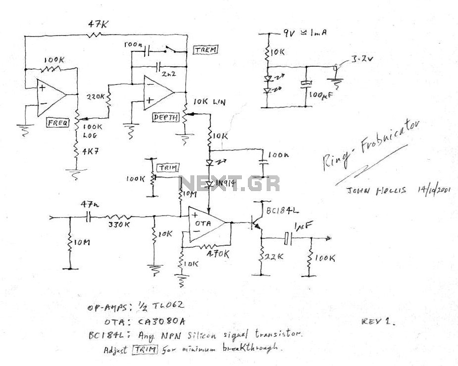
Guitar Vibrato circuit
The circuit in question is designed to function as a phase shifter, which is a critical component in various electronic applications, including signal processing and communication systems. The operational amplifier (op-amp) configuration used in this circuit typically consists of resistors and capacitors that determine the phase shift characteristics. When implementing this circuit, it is essential to select components that minimize noise and distortion to maintain signal integrity.
The use of Field-Effect Transistors (FETs) in this design is significant due to their high input impedance and low output impedance, which are advantageous for maintaining signal fidelity. However, the matching of FETs is crucial because mismatched devices can lead to phase errors and degrade performance. When utilizing off-the-shelf FETs, careful consideration must be given to their specifications to ensure compatibility with the circuit's requirements.
In terms of the setup process, it may involve adjusting the biasing conditions and feedback components to achieve the desired phase shift. This may require iterative testing and measurement to fine-tune the circuit. The critical parameters to monitor include the gain, phase shift, and linearity of the output signal. It is advisable to use precision variable resistors to allow for fine adjustments during the calibration phase.
Overall, while the circuit's design is straightforward, the challenges associated with component selection and setup necessitate a thorough understanding of the operational principles and characteristics of the devices involved. Proper execution of this circuit can lead to effective phase shifting capabilities, suitable for a variety of electronic applications.The circuit of the unit is fairly simple, but is a bit irksome to set up. The reason is that obtaining matched FETs is not easy, so I had to make sure that the circuit would work with off-the-shelf FETs. The phase shifter is a standard opamp circuit, and has been used for this sort of application many times.
After experimenting with alternative va riable resistors, I decided that the FET was still the best choice, although they are fairly critical to set up, and have linearity problems. 🔗 External reference
Related Circuits
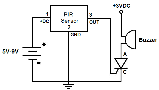
This is an alarm circuit that activates when motion is detected. Upon detection, the circuit triggers an alarm buzzer, which remains activated until the power is disconnected. This type of alarm circuit is commonly used to monitor areas for...
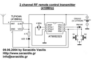
The following circuit illustrates a 3V power supply designed for an RF remote control circuit. This circuit is based on the AT90S2323 integrated circuit (IC). Features include a data rate of 2400 bps. The 3V power supply circuit for the...
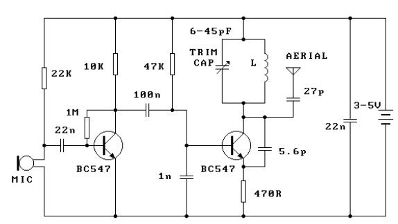
This FM transmitter circuit is very simple and has an acceptable transmission range. The signal transmitted from this FM transmitter circuit can be received at almost 300 meters in open air. The circuit requires a 3-volt operating voltage and...
In certain versions of the circuit, the input buffer may be completely absent, while in other versions, the buffer transistors exhibit different biasing configurations or utilize different transistors altogether. Some designs contain significant errors, including biasing issues and incorrect...
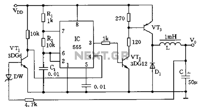
The circuit consists of a 555 timer configured as an astable multivibrator along with resistors R1 and R2 and capacitor C1. It generates an oscillation frequency of approximately 10 kHz with a duty cycle close to 50%. Transistors VT2...
This schematic illustrates a beeper circuit designed to produce a continuous beep sound while simultaneously flashing an LED. The beeper circuit typically consists of a few key components: a sound-generating device (such as a piezo buzzer), an LED for visual...