Analog Signal Transmission Through DC Supply Line
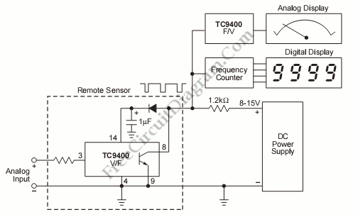
If the sensor system requires an active supply, a single pair of cables can be utilized to transmit both the power supply and the output signal. This approach simplifies the overall system.
In sensor systems that necessitate an active power supply, employing a single pair of cables for both power and signal transmission offers significant advantages. This method, often referred to as Power over Ethernet (PoE) in network applications or similar approaches in sensor networks, reduces the complexity of wiring and installation.
The design typically involves using a twisted pair of wires, which can effectively minimize electromagnetic interference and maintain signal integrity over distances. The power supply is often injected into one of the conductors while the output signal is transmitted over the other. This dual-use of cabling not only reduces the amount of physical wiring required but also simplifies the installation process, particularly in environments where space is limited or where multiple sensors need to be deployed.
To implement this system, careful consideration must be given to the voltage and current requirements of the sensor, ensuring that the cable can handle the necessary power without significant losses. Additionally, the output signal type—whether analog or digital—should be compatible with the transmission medium to ensure reliable communication between the sensor and the receiving unit.
In summary, utilizing a single pair of cables for both power and signal in sensor systems streamlines the installation process, reduces material costs, and can enhance system reliability when designed with appropriate specifications.If the sensor system need an active supply, we can use only a single pair of cable to carry both the power supply and the output signal. Not only simplify the. 🔗 External reference
