
Simple Analogue Electronic Key
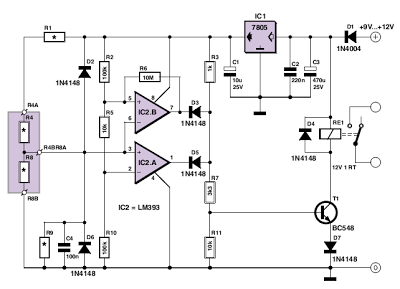
The window comparator circuit operates by comparing the voltage levels at its inputs. The arrangement of resistors R2, R5, and R10 creates a defined voltage range that the input voltage must fall within for the comparators to output high signals. This functionality is critical for applications where precise voltage thresholds need to be monitored, such as in locking mechanisms. The use of transistors and relays allows for the control of higher power devices, such as electric latches, based on the comparator signals.
The potential divider formed by resistors R1, R4, R8, and R9 is integral to setting the correct voltage at the junction of D2 and D6. The careful selection of these resistor values ensures that the voltage remains within the defined window, allowing the circuit to function as intended. The flexibility in choosing these resistor values is advantageous, as it permits customization of the locking mechanism for different applications or security requirements.
Furthermore, the stability of the power supply is ensured by the voltage regulator IC1, which maintains a constant 5 V output. This stability is crucial for the reliable operation of the comparators and the entire circuit. Any fluctuations in the supply voltage could lead to false triggering or failure of the locking mechanism.
In summary, this circuit exemplifies a practical application of comparators in a security context, demonstrating how careful design and component selection can lead to effective and customizable electronic solutions. The relationships between the resistors provide a framework for users to tailor the circuit to their specific needs while ensuring reliable operation.This circuit uses two comparator that are combined in what is called a window comparator, i. e. resistors R2, R5, and R10 determine a voltage window within which the voltage applied to the junction of D2 and D6 must lie in order for the outputs of IC2. A and IC2. B to both be high at the same time. Given the value used for these resistors, this windo w is from 10/21 to 11/21 of the comparator supply rail (5 V). If IC2. A and IC2. B outputs are both high at the same time, transistor T1 is saturated via the AND gate formed by D3 and D4, and relay RE1 is energized to operate the electric latch or any other locking device. The key is defined by the generation of the specif ic voltage at the junction of D2 and D6, formed, for example, by a simple stereo jack containing the two resistors R4 and R8.
Together with R1 and R9, they form a potential divider that needs to be suitably calculated in conjunction with the values of R2, R5, and R10 so that the key can open the lock. Clearly, all this will only work correctly is the supply voltage to these two dividers is stable, which is ensured by IC1, regulating it to 5 V.
If we had set the values for R1 and R9, all the readers of this edition of Elektor would have had the same key, which is clearly not a good idea! So you need to decide for yourself not only R4 and R8, which form the key, but also R1 and R9 which let you customize the lock`.
1 Here are the relationships between the values of resistors R1, R4, R8, and R9 for the key to be able to open the lock: Note too that, as the relationships consist of inequalities, and that there are only two (un)equations for four unknowns, this leaves quite a wide choice for the resistor values. We advise you to set at least two of them to preferred values, which will then let you work out the others.
If, as is more than likely, this does not result in other preferred values, you`ll then need to use series/parallel combinations to obtain the calculated values or else choose different starting values in order to arrive at a better compromise. 🔗 External reference
Related Circuits
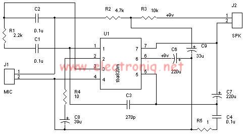
A very simple audio amplifier circuit can be designed using the TBA820M audio amplifier integrated circuit with just a few electronic components. This audio amplifier project features a high gain that allows for the detection of sounds underwater. The...
The circuit is capable of enhancing the system power factor to a value exceeding 0.99. It effectively reduces the waveform distortion of the input supply current, ensuring compliance with GB15144 standards, with a distortion index lower than level L....
The following circuit illustrates a simple battery charger equipped with a temperature sensor. This circuit is based on the LM350 integrated circuit. Features include negative... The circuit utilizes the LM350 voltage regulator IC, which is known for its ability to...
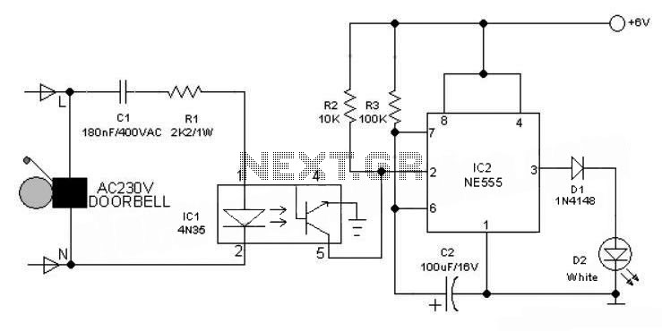
This 6V battery-operated doorbell light circuit can be connected in parallel with any existing AC 230V doorbell. When the doorbell switch is pressed, the bell sounds as usual, and the AC mains supply available across the doorbell is routed...
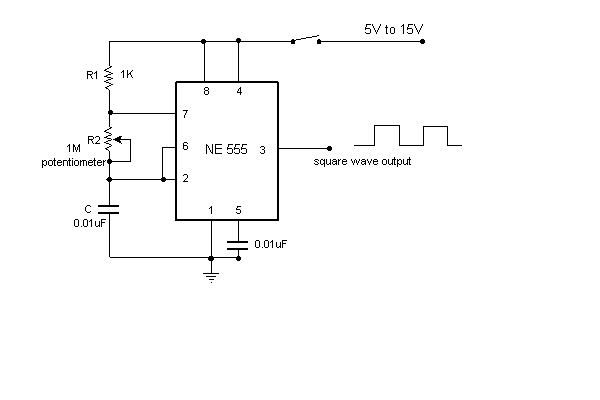
A simple variable frequency oscillator utilizing a 555 timer IC to generate a square wave frequency that can be adjusted using a potentiometer. The circuit operates primarily on the principles of astable multivibrator configuration using the 555 timer IC, which...
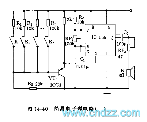
The controllable multivibrator, as illustrated in figure 14-40, consists of a 555 timer along with resistors RA, RP1, and capacitor C1. The oscillation frequency is influenced by the control voltage applied to pin 5. This control voltage is determined...