
Simple Audio amplifier Using Transistors
The design of a simple audio amplifier using transistors typically involves a few key components: the transistors themselves, resistors, capacitors, and a power supply. The most common transistor types used in audio applications are bipolar junction transistors (BJTs) or field-effect transistors (FETs).
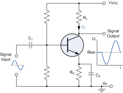
The basic configuration for a transistor amplifier is the common emitter configuration, which provides voltage gain. In this setup, the input signal is applied to the base of the transistor, and the output is taken from the collector. A resistor is connected to the collector to convert the varying current into a voltage signal. The emitter is usually connected to ground through an emitter resistor, which helps stabilize the operating point of the transistor.
To enhance the performance of the amplifier, coupling capacitors are often used at the input and output stages. These capacitors block any DC offset from the input signal while allowing the AC audio signal to pass through. Additionally, bypass capacitors can be employed across the emitter resistor to increase gain at higher frequencies.
Power supply considerations are crucial for ensuring that the amplifier operates within the desired voltage range. A dual power supply configuration (positive and negative voltages) is commonly used to allow for a symmetric output signal, which is particularly important for audio applications.
In summary, building a simple audio amplifier with transistors involves understanding the fundamental principles of transistor operation, selecting appropriate components, and designing the circuit layout to achieve the desired amplification characteristics. Resources such as Rod Elliott's article can provide valuable theoretical insights, while practical experimentation will enhance comprehension of transistor behavior in amplification applications.Build a simple audio amplifier using transistors. I know there are IC designs specifically for the task. But i want to use transistors so i can learn how to use them for amplification. Amplifier Basics - How Amps Work (Intro) by Rod Elliott covers a good percentage of the basics of using transistors as an amplifier. It is not a construction article, but focuses on explaining the basics. mctylr Jul 26 `12 at 18:24 🔗 External reference
Related Circuits
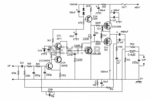
In this circuit we use the 2SK1058 and the 2SJ162 Mosfets. This could be avoided by a fairly simple bootstrapping circuit, but the improvement in maximum output may be just a fraction of a dB, depending on the supply...
The BFP640 transistor is utilized for 1575 MHz Global Positioning Satellite (GPS) applications, specifically as a Low Noise Amplifier (LNA). The design objectives include a minimum gain of 16 dB, a noise figure of less than 0.6 dB, an...
The audio mixer allows for easy comparison of various receivers by adjusting the gain controls without the need for switching. This setup simplifies A/B comparisons since all receivers are connected to the same antenna. Previously, different speakers were used...
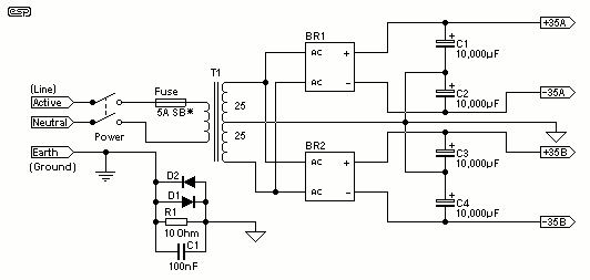
For the 60W amplifier, a nominal (full load) supply of +/- 35V is required, so a 25-0-25 secondary is ideal - however, see Updates, below. The circuit for the supply is shown below, and uses separate rectifiers, capacitors and...
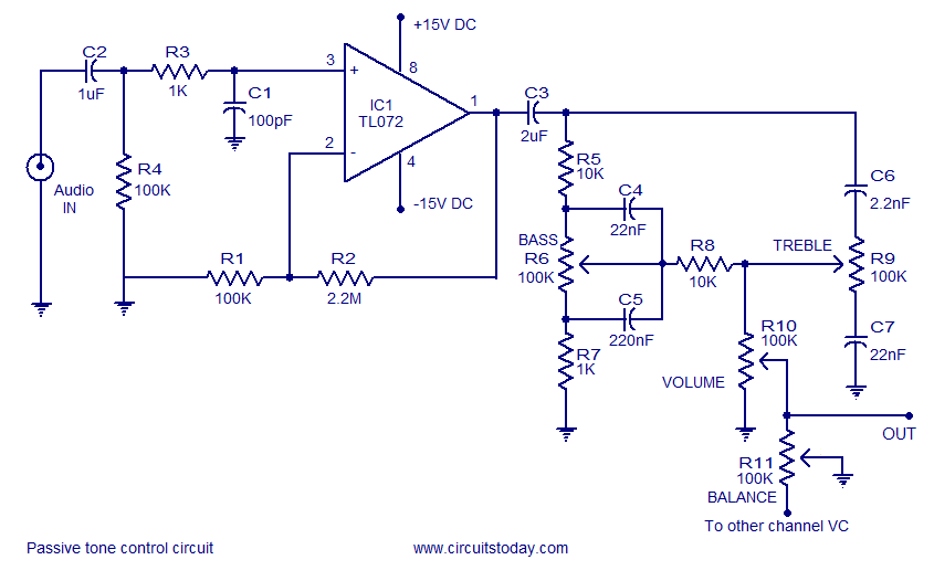
Tone control circuit utilizing an operational amplifier and a Baxandall passive tone control configuration. The overall gain is 25 dB, with a boost and cut capability of 20 dB. The circuit is powered by a dual 15V supply. The tone...
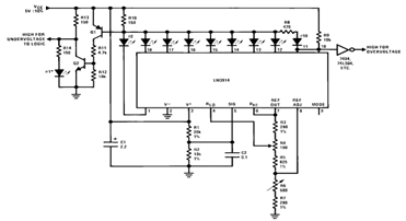
By utilizing several resistors, LEDs, and the LM3914 bar/dot display driver IC, it is possible to create a straightforward 5V voltmeter monitor circuit. This circuit offers TTL-compatible undervoltage and overvoltage warning signals. A complete circuit schematic is available below. The...
Warning: include(partials/cookie-banner.php): Failed to open stream: Permission denied in /var/www/html/nextgr/view-circuit.php on line 713
Warning: include(): Failed opening 'partials/cookie-banner.php' for inclusion (include_path='.:/usr/share/php') in /var/www/html/nextgr/view-circuit.php on line 713