
100W Mosfet Power Amplifier
Ideally the output stage operating voltage should be adjusted using the 10k preset by checking for symmetrical clipping using an oscilloscope, but failing this it should be good enough to set the voltage with no signal to about half the supply voltage with the amplifier at its normal operating temperature. The negative output swing is reduced by the cascode stage, while the positive swing is reduced by the falling supply voltage at high output levels, so hopefully these effects will be approximately equal, giving something not too far from symmetry. Music signals are mostly asymmetric, giving greater clipping on one polarity or the other, so there is no point trying to be exact about this. If clipping occurs regularly you need a higher power amplifier anyway.
There is excellent supply rejection. The input stages have no direct link to the supply, and the high feedback will greatly reduce any breakthrough in later parts of the circuit. The distortion observed appeared to have no supply related components above the noise level. The 3V6 zener has a fairly high impedance at 1mA, typically 400R, and some theoretical improvement in supply rejection could be gained by using a ZRC330 3V3 voltage reference, or alternatively two red leds in series.
For best results with either mosfet amplifier design, it is suggested to avoid capacitive loads above 4uF and to avoid high input signal source impedance (3k or less should be no problem; if driven directly from a volume control, this could be 10k or 5k log). It is important to distinguish between 'stability' and 'unconditional stability'. The fact that an amplifier fails to oscillate with any reasonable load is no guarantee of stability because the loop gain changes near to clipping, so that the unity gain frequency, where oscillation can occur, can shift downwards. To ensure this has no unpleasant consequences, it is advisable to keep the phase lag around the feedback loop under 180 degrees at any frequency up to and a little beyond the loop unity gain frequency. An amplifier's internal open-loop output impedance may be significantly inductive at some frequencies, and with a capacitor load, the resulting phase shift can approach 180 degrees without any additional effect from compensation capacitors. The output inductor is approximately 0.4uH (13 turns of 1.2mm enamelled copper wire with an inside diameter of 1cm and a winding length of 16mm) and is intended to reduce the effects of capacitive loads at high frequencies, but it has limited impact in the audio frequency range.
High frequency compensation utilizes a capacitor from the driver stage output to ground, which has the advantage of being minimum phase, whereas the more common 'Miller' feedback capacitor method is not. In a typical circuit, the Miller method can introduce additional high frequency phase shift for a given attenuation, particularly with low stage gain or near clipping where the stage gain falls. The question of whether the driver stage or the output stage clips first is critical for this effect. The feedforward effect was discussed by Baxandall in his 1978 Wireless World series.
The shunt feedback inverting circuit avoids common-mode input distortion, which would not be mitigated by feedback. The 10pF capacitor in parallel with the 220k feedback resistor is essential for stability, as any radio frequency interference picked up by the speaker or its cable could be fed back to the input stage with minimal attenuation. In this context, the capacitor serves to more accurately define the feedback level at high frequencies where the feedback through a 220k resistor is unpredictable due to stray capacitance. The combination of the 10pF and the 390pF from the input base to ground forms a potential divider that attenuates any interference by a factor of 40.
Excluding the output inductor can result in an additional open-loop 80-degree phase shift at the unity gain frequency, which is undesirable. This has been demonstrated, along with further information about loop stability, interference rejection, and board layout. Stability could still be improved further, but the version described has been built and tested with no obvious problems. Reports of instability with small capacitive loads have been noted, leading to changes in one compensation component, and an optional 100n capacitor has been added across the output to ensure that the series resonance frequency with the output inductor is maintained well below the unity gain frequency.In this circuit we use the 2SK1058 and the 2SJ162 Mosfets. This could be avoided by a fairly simple bootstrapping circuit, but the improvement in maximum output may be just a fraction of a dB, depending on the supply voltage used, so too small to notice. The temperature coefficient of the output stage d.c. operating level can have a further small effect on available output, which again may be too small to be worth worrying about.
Any drift will be very slow, and with capacitor coupled output this is not a problem. My own amplifier runs only slightly warm with a 60V supply, and the drift in operating point between cold and normal operating temperature gives less than a 1V variation from the optimum level for symmetric clipping. This would reduce maximum unclipped sine wave power by only 0.4dB. I am reluctant to add temperature compensation partly because I want to keep the design simple. To avoid additional components just replacing the 47k d.c. feedback resistor with a PTC thermistor seems obvious, but a quick calculation suggests problems with self-heating. A transistor in the d.c. feedback network has been suggested to me, which may work well, but adding a nonlinear component in the feedback network is something I prefer to avoid.
My current favourite is a circuit using the LM19 temperature detector (1V5 at 25 deg.C, -11mV/deg.C, 3 pin TO-92, cost 35p.). In practice, unless a stabilised supply is used the positive supply voltage is variable, and so even a perfectly constant 'mid-point' voltage will not ensure accurate symmetrical clipping, so it is a questionable 'improvement'.
Ideally the output stage operating voltage should be adjusted using the 10k preset by checking for symmetrical clipping using an oscilloscope, but failing this it should be good enough to set the voltage with no signal to about half the supply voltage with the amplifier at its normal operating temperature. The negative output swing is reduced by the cascode stage, while the positive swing is reduced by the falling supply voltage at high output levels, so hopefully these effects will be approximately equal, giving something not too far from symmetry.
Music signals are mostly asymmetric, giving greater clipping on one polarity or the other, so there is no point trying to be exact about this. If clipping occurs regularly you need a higher power amplifier anyway. There is excellent supply rejection. The input stages have no direct link to the supply, and the high feedback will greatly reduce any breakthrough in later parts of the circuit.
The distortion observed appeared to have no supply related components above the noise level. The 3V6 zener has a fairly high impedance at 1mA, typically 400R, and some theoretical improvement in supply rejection could be gained by using a ZRC330 3V3 voltage reference, or alternatively two red leds in series. For best results with either mosfet amplifier design I suggest avoiding capacitive loads above 4uF and avoiding high input signal source impedance (3k or less should be no problem, if driven direct from a volume control this could be 10k or 5k log).
It is important to distinguish between 'stability' and 'unconditional stability'. The fact that an amplifier fails to oscillate with any reasonable load is no guarantee of stability because the loop gain changes near to clipping, so that the unity gain frequency, where oscillation can occur, can shift downwards, and to ensure this has no unpleasant consequences it is a good idea to try to keep the phase lag round the feedback loop under 180deg at any frequency up to and a little beyond the loop unity gain frequency. An amplifier's internal open-loop output impedance may be significantly inductive at some frequencies, and with a capacitor load the resulting phase shift can in principle already approach 180deg without any additional effect from compensation capacitors etc.
The effect of load impedance can be a serious problem for high feedback designs simply because the load to be used is unknown and therefore could cause phase shift at any frequency. The output inductor is about 0.4uH (13 turns 1.2mm enamelled copper wire with inside diameter 1cm and winding length 16mm) and is intended to reduce the effects of capacitive loads at high frequencies, but can do little to help in the audio frequency range.
The high frequency compensation uses a capacitor from the driver stage output to earth, which has the advantage of being minimum phase, whereas the more common 'Miller' feedback capacitor method is not, and in a typical circuit can add extra high frequency phase shift for a given attenuation because of feedforward through the capacitor, which is usually a small effect, but can be more serious with low stage gain, or near clipping where the stage gain falls, which as mentioned above is where stability can already be a problem. The question of whether the driver stage or the output stage clips first is critical for this effect.
The feedforward effect was mentioned by Baxandall in his 1978 Wireless World series. The shunt feedback inverting circuit avoids common-mode input distortion, which would not be reduced by the feedback. The 10pF capacitor in parallel with the 220k feedback resistor would normally be a problem because any radio frequency interference picked up by the speaker or its cable could be fed back to the input stage with little attenuation.
A capacitor is often added in this position to improve stability by cancelling some of the phase lag round the feedback loop, but here it has an entirely different purpose, which is to more accurately define the feedback level at high frequencies where the feedback through a 220k resistor is not easily predictable because of stray capacitance. The 10pF and the 390pF from input base to earth form a potential divider which will attenuate any interference picked up by a factor of 40.
Leaving out the output inductor can result in an extra open-loop 80deg phase shift at the unity gain frequency, which we certainly want to avoid. This is demonstrated, plus additional information about loop stability, interference rejection, and board layout HERE.
Stability could still be improved further, but the version shown here has been built and tested and found to have no obvious problems. I have a report of instability with small capacitive loads, which I had missed, and there is now a change in one compensation component, and there is an optional 100n capacitor added across the output so that the series resonance frequency with the output inductor is kept well below the unity gain frequency.
🔗 External reference
Related Circuits
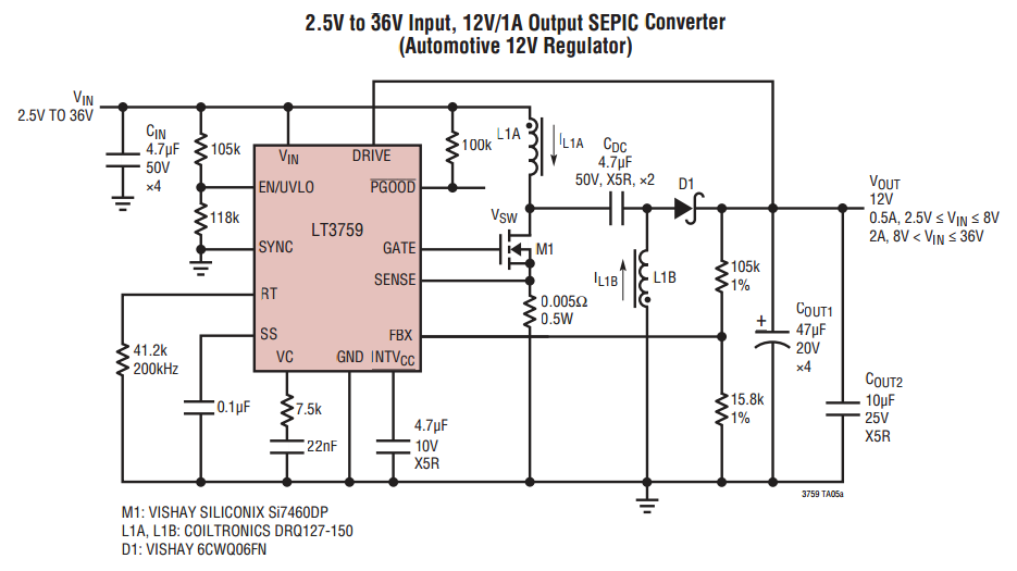
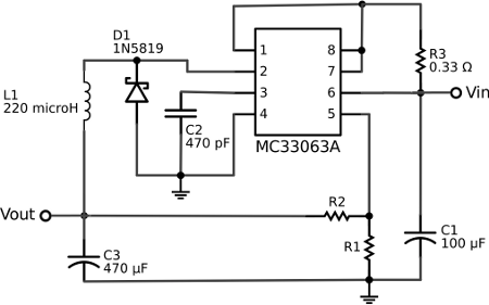
When VOUT is very low during startup or in the event of a short-circuit fault at the output, the switching regulator must operate at low duty cycles to keep the power switch current within the current limit range. This...
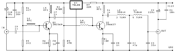
This project involves a 250mW RF power amplifier circuit. It is designed to amplify the output of approximately 7mW wideband FM transmitters to a final output level of about 250mW. The circuit utilizes a simple two-transistor VHF power amplifier...
This project was a surprise as the BC547 transistor (equivalent to 2N2222) can be used to construct a 500mW linear amplifier that operates across the entire HF band with excellent spectral purity and without the need for neutralization. The...
The voltage regulator integrated into the Arduino Uno is a linear-type regulator, which exhibits poor efficiency. When operating the ATmega238 at 5V with a 9V battery, nearly half of the battery's energy is wasted as heat by the regulator....
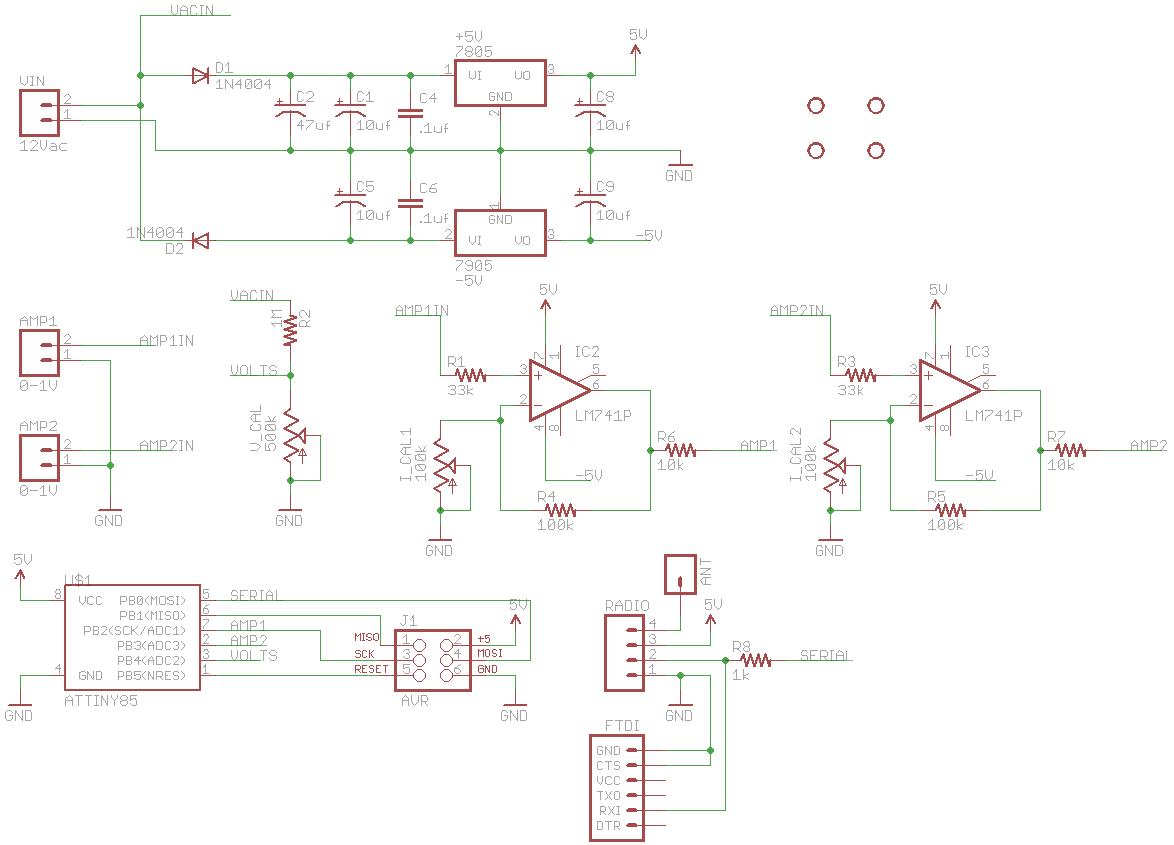
The Kill A Watt is a product that measures volts, amps, and power factor of individual appliances, allowing users to calculate power consumption and running costs. However, a desire for a solution that provides similar data for an entire...
China's national conditions indicate that the general living room area exceeds twenty square meters, often serving as a bedroom or listening room. For speakers with a sensitivity of 89 dB or higher, a pure Class A amplifier with a...
Warning: include(partials/cookie-banner.php): Failed to open stream: Permission denied in /var/www/html/nextgr/view-circuit.php on line 713
Warning: include(): Failed opening 'partials/cookie-banner.php' for inclusion (include_path='.:/usr/share/php') in /var/www/html/nextgr/view-circuit.php on line 713